
A two-phase bubbly flow mixing device and method at the bottom inlet of a vertical rod bundle channel

A technology of rod bundle channel and bubbly flow, which is applied to the field of two-phase bubbly flow mixing device at the bottom of vertical rod bundle channel, can solve the problems of device vibration, large flow resistance, increase vapor phase solubility, etc. The effect of frame vibration, uniform force and impact avoidance

Active Publication Date: 2020-05-15
XI AN JIAOTONG UNIV
View PDF3 Cites 0 Cited by
  • Summary
  • Abstract
  • Description
  • Claims
  • Application Information

AI Technical Summary

Problems solved by technology

For example, Chinese patent CN102068928A discloses a vapor-liquid two-phase flow mixer. The device is a bidirectional conical structure with opposite-spinning rifles arranged on the inside, which can break the bubbles in the two-phase flow and achieve fine particle size. However, the main purpose of the device is to effectively increase the surface area of ​​the vapor-liquid interface to increase the solubility of the vapor phase. It is not suitable for the study of the characteristics of the two-phase bubbly flow pattern, and the experimental device cannot Achieve better uniformity of bubbles
Chinese patent CN204142465U discloses a gas-liquid two-phase flow phase holdup control and gas-liquid two-phase mixing device, the device includes structures such as liquid delivery pipeline, gas delivery pipeline and gas-liquid two-phase mixer, wherein The device is a double-layer cylinder structure, and the gas-liquid two-phase is mixed through the air inlet holes arranged on the inner wall of the cylinder. The device can adjust the gas-liquid two-phase flow through the flow meter and the regulating valve to control the gas-liquid two-phase flow in a stable state. However, the mass flow rate of the liquid in this device cannot be too large, otherwise the uniformity of the bubbles cannot be guaranteed, so this device is not suitable for the experimental research on the characteristics of two-phase bubbly flow under the condition of large flow rate, and The range of gas holdup ratio in the experiment is also limited
However, the flow resistance of this corrugated plate structure is relatively large, and the stability of the device under large flow rates cannot be guaranteed, which may cause vibration of the device

Method used


Image

  • A two-phase bubbly flow mixing device and method at the bottom inlet of a vertical rod bundle channel
  • A two-phase bubbly flow mixing device and method at the bottom inlet of a vertical rod bundle channel
  • A two-phase bubbly flow mixing device and method at the bottom inlet of a vertical rod bundle channel

Examples


Embodiment Construction

[0027] The method of the present invention will be described in detail below in conjunction with the accompanying drawings and specific embodiments.

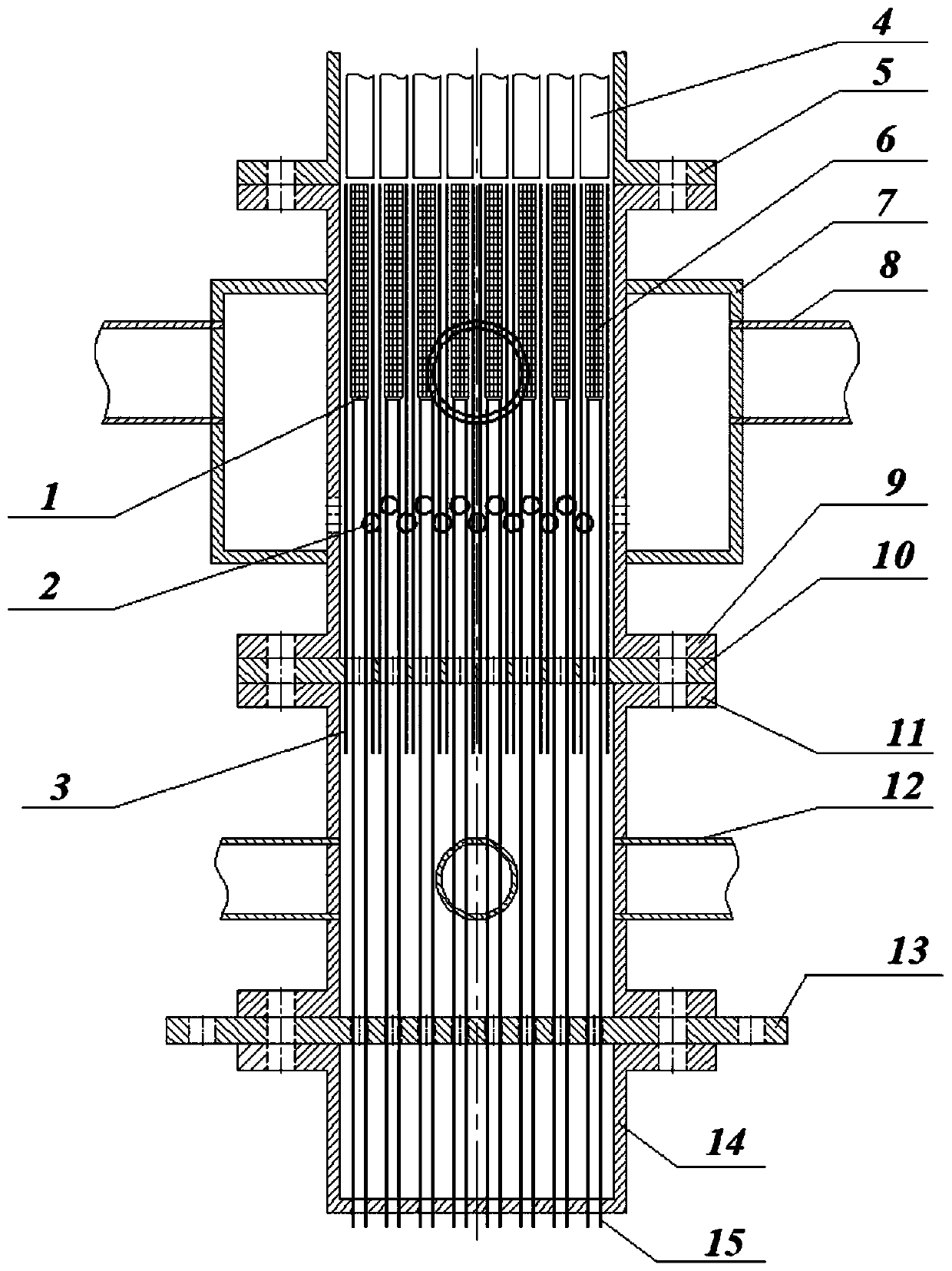
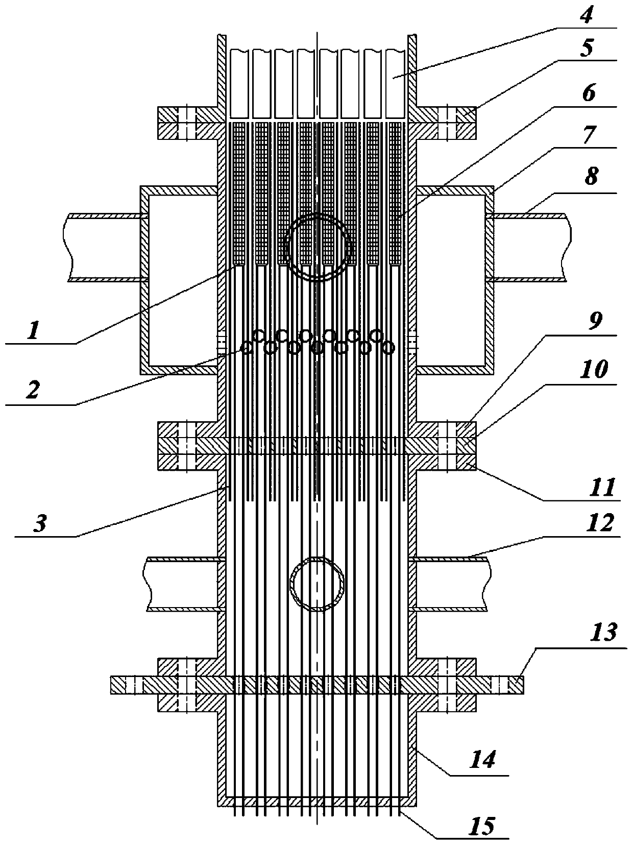
[0028] Such as figure 1 As shown, a two-phase bubbly flow mixing device at the bottom of the vertical rod bundle channel of the present invention includes a filter element transition section 1, a main water inlet hole 2, a filter element sleeve 3, an experimental rod bundle 4, a rod bundle sleeve 5, Porous section of filter element 6, main water inlet chamber 7, main water inlet pipe 8, device upper pipe seat 9, filter element sleeve fixing plate 10, auxiliary water inlet chamber 11, auxiliary water inlet pipe 12, filter element fixing plate 13, device lower pipe Seat 14 and filter core tube section 15.

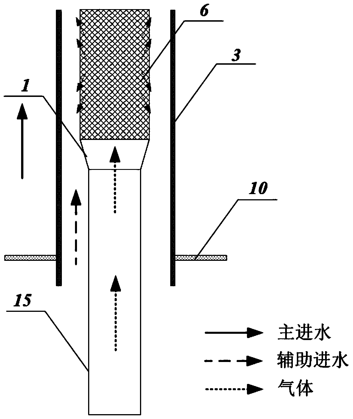
[0029] Such as figure 2 As shown, the filter element circular tube section 15, filter element transition section 1 and filter element porous section 6 are the basic components of the filter element structure, and are the cir...


PUM


Abstract

A two-phase bubbly flow mixing device and method at the bottom inlet of a vertical rod bundle channel. The auxiliary water inlet area composed of the auxiliary water inlet chamber, the filter element structure composed of the filter element circular tube section, the filter element transition section and the filter element porous section, and the device consisting of the upper and lower pipe seats of the device, the filter element casing, the filter element fixing plate and the filter element casing fixing plate Support and fixed structure; after the gas enters from the round pipe section of the filter element, it flows out from the porous section of the filter element through the transition section of the filter element and mixes with the auxiliary water inlet to flow upward. The gas-liquid two-phase formed by mixing is then mixed with the main water inlet. Obtain bubbly two-phase flow with different gas content, and finally enter the rod bundle channel area; the present invention can obtain a larger range of bubbly two-phase flow, satisfying the two-phase bubbly flow for different vapor content in the rod bundle channel Experimental requirements; in addition, the present invention also has the advantages of simple operation, high stability, and easy processing and installation of the device.

Description

technical field [0001] The invention belongs to the technical field of two-phase bubbly flow experiment research, and in particular relates to a two-phase bubbly flow mixing device and method at the bottom inlet of a vertical rod bundle channel. Background technique [0002] Gas-liquid two-phase flow is widely used in industries such as petroleum, chemical industry, energy, power, aerospace systems, and pharmaceuticals. It usually contains complex and variable flow patterns, including bubbly flow, slug flow, annular flow, and mist flow. etc. It is of great significance to study its flow pattern characteristics in the production process and scientific research. [0003] In the experimental research of gas-liquid two-phase bubbly flow, the first problem to be solved is the formation of bubbly flow and the mixing of gas-liquid two-phase. The usual method is to add special equipment for gas-liquid mixing on the gas-liquid two-phase flow circuit. , but due to the complexity of g...

Claims


Application Information

Patent Timeline
Patent Type & Authority Patents(China)
IPC IPC(8): B01F13/10B01F5/00B01F3/04
CPCB01F23/235B01F23/291B01F23/29B01F25/00B01F33/82B01F2101/23
Inventor 田文喜桂民洋张魁章静秋穗正苏光辉
Owner XI AN JIAOTONG UNIV
Learn More