Power ultrasound promoted light material separating device for soil remediation device
A soil remediation and separation device technology, applied in the field of soil remediation, can solve the problems of low separation efficiency and waste, and achieve the effect of ensuring recovery rate, avoiding waste, and ensuring the contact recovery area of light materials
- Summary
- Abstract
- Description
- Claims
- Application Information
AI Technical Summary
Problems solved by technology
Method used
Image
Examples
specific Embodiment approach 1
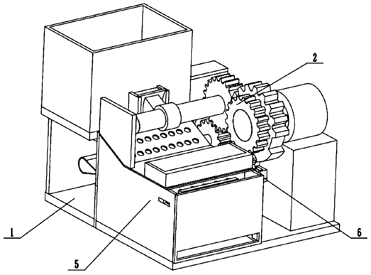
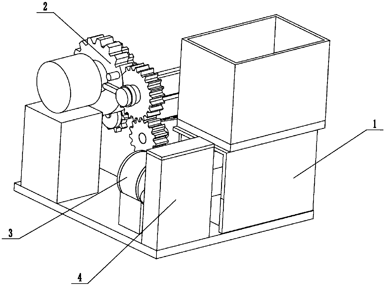
[0030] Such as Figure 1~Figure 11 As shown, the power ultrasound promotes the light material separation device for the soil remediation device, including the storage box seat 1, the discharge drive 2, the light material exhaust fan 3, the light material recovery box 4, the material separation box 5 and the heavy material discharge switch 6 , The light material exhaust fan 3, the discharge driver 2, the light material recovery box 4 and the material separation box 5 are all fixedly connected to the storage box seat 1, and the left end of the discharge driver 2 is slidably connected to the storage box seat 1, the discharge drive 2 is rotatably connected to the material separation box 5. The left end of the light material exhaust fan 3 is connected to the light material recovery box 4 through a pipe, and the right end of the light material exhaust fan 3 is fixedly connected to the left end of the material separation box 5. The substance exhaust fan 3 is connected to the inside of...
specific Embodiment approach 2
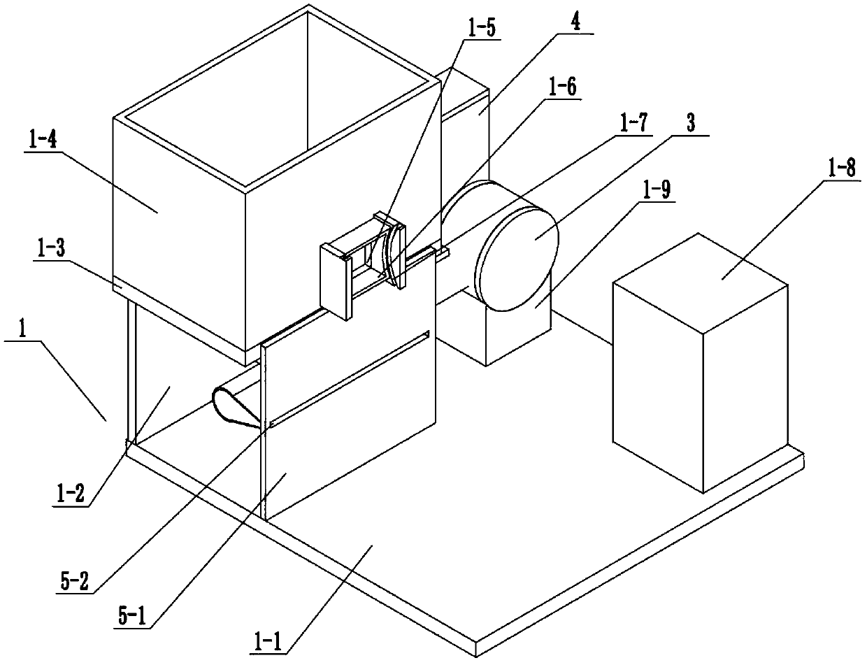
[0031] Such as Figure 1~Figure 11 As shown, this embodiment will further illustrate the first embodiment. The storage box seat 1 includes a bottom plate 1-1, a left vertical plate 1-2, an upper bottom plate 1-3, a storage box 1-4, and a discharge opening. 1-5, discharge port fixed block 1-6, two arc-shaped chute 1-7, motor base 1-8 and exhaust fan base 1-9, the left vertical plate 1-2 is fixedly connected to the bottom plate 1-1 The left end of the upper bottom plate 1-3 is fixedly connected to the left vertical plate 1-2, the right end of the upper bottom plate 1-3 is fixedly connected to the substance separation box 5, and the storage box 1-4 is fixedly connected to the upper bottom plate 1-3. On the upper side, the right end of the storage box 1-4 is provided with a discharge port 1-5, the discharge port fixing block 1-6 is fixedly connected to the right end of the storage box 1-4, and the discharge port fixing block 1-6 communicates with the discharge Ports 1-5, two arc-s...
specific Embodiment approach 3
[0032] Such as Figure 1~Figure 11 As shown, this embodiment will further illustrate the second embodiment. The light material suction fan 3 includes a blower 3-1, a tapered tube 3-2, a plurality of partition plates 3-3, and a connecting tube 3-4. The blower 3-1 is fixedly connected to the exhaust fan base 1-9, the tapered pipe 3-2 is connected to the air inlet of the blower 3-1 through the connecting pipe 3-4, and the air outlet of the blower 3-1 is connected to the light material recovery box 4. An opening is provided at the right end of the tapered tube 3-2, and a plurality of tapered tubes 3-2 are uniformly fixedly connected in the opening. The blower 3-1 is an existing technology, and it can be used by selecting M7-16.
PUM
 Abstract
Description
Claims
Application Information
 - R&D
- Intellectual Property
- Life Sciences
- Materials
- Tech Scout
- Unparalleled Data Quality
- Higher Quality Content
- 60% Fewer Hallucinations
Browse by: Latest US Patents, China's latest patents, Technical Efficacy Thesaurus, Application Domain, Technology Topic, Popular Technical Reports.
© 2025 PatSnap. All rights reserved.Legal|Privacy policy|Modern Slavery Act Transparency Statement|Sitemap|About US| Contact US: help@patsnap.com


