Al technical title is built by PatSnap Al team. It summarizes the technical point description of the patent document.
A technology of a hydraulic system and a cleaning device, which is applied in the direction of using liquid cleaning methods, cleaning hollow objects, cleaning methods and appliances, etc., and can solve problems such as joint blockage, retention, and oil pollution
Active Publication Date: 2022-05-10
SHANDONG UNIV OF TECH
View PDF6 Cites 0 Cited by
Summary
Abstract
Description
Claims
Application Information
AI Technical Summary
This helps you quickly interpret patents by identifying the three key elements:
Problems solved by technology
Method used
Benefits of technology
Problems solved by technology
[0002] After the tractor hydraulic system is assembled, there will be impurities in the hydraulic pipelines and hydraulic components; secondly, due to the harsh working environment in the field, after the tractor is working, it is inevitable that dust and debris will enter the hydraulic system of the tractor, and then As the working time of the hydraulic system increases, the oil will also be polluted accordingly
In the actual use of the tractor, the user only relies on the filter element in the system to control the pollution degree of the hydraulic system. Since the user does not clean and replace the filter element in time, the precision components of the hydraulic system, such as control valves and joints, are often blocked, resulting in The oil temperature rises, seriously affecting the service life of the tractor
Method used
Image
Click on the blue label to locate the original text in one second.
Reading with bidirectional positioning of images and text.
Examples
Embodiment Construction
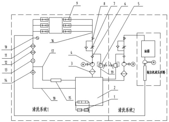
[0009] Attached below figure 1 , attached figure 2 The specific implementation of the tractor hydraulic system cleaning device will be further described. Such as figure 1 , when the cleaning system is used to clean a pair of hydraulic components, first connect the inlet and outlet ports of the hydraulic components to the oil inlet and oil return circuits of the quick-change joint group 9 through the auxiliary oil pipe, and turn on the motor switch of the motor pump group 4 , start the cleaning system, at this time the hydraulic pump of the motor pump group 4 pumps the hydraulic oil in the cleaning oil tank 2 into the system through the oil suction filter 3, and the hydraulic oil passes through the overflow pipeline 19, the check valve 6, the check joint Flow valve 7, quick-change joint group 9, circulating crude oil filter 11, circulating essential oil device 12, flow meter 13, cooler 14, and oil return pipeline 18 flow back into the cleaning oil tank 2 to form a circulatin...
PUM
Abstract
A tractor hydraulic system cleaning device belongs to the technical field of agricultural machinery equipment. Mainly used for cleaning tractor hydraulic system and hydraulic components. The device is composed of cleaning system 1, cleaning system 2 and control system. System 1 is a hydraulic component cleaning system, which consists of cleaning oil tank, heating system, motor pump unit, proportional overflow valve, flow control valve, quick change joint group, It consists of a pressure gauge, a combined filter device, a cooler, and an online pollution detection device; the cleaning system 2 is a tractor hydraulic system circuit cleaning system, which is composed of a motor pump unit, a proportional overflow valve, and a flow control valve. The control system consists of a controller, cleaning status Display device, cooling control device, heating control device, pollution degree detection device, proportional pressure regulating system and temperature, pressure, flow sensor, in order to complete the cleaning system for the cooler, heater, cleaning time, cleaning pressure and temperature, pressure, Flow display control.
Description
technical field [0001] The invention provides a tractor hydraulic system cleaning system, which belongs to the technical field of agricultural machinery equipment. Mainly used for cleaning tractor hydraulic system and hydraulic components. Background technique [0002] After the tractor hydraulic system is assembled, there will be impurities in the hydraulic pipelines and hydraulic components; secondly, due to the harsh working environment in the field, after the tractor is working, it is inevitable that dust and debris will enter the hydraulic system of the tractor, and then As the working time of the hydraulic system increases, the oil will also be polluted accordingly. In the actual use of the tractor, the user only relies on the filter element in the system to control the pollution degree of the hydraulic system. Since the user does not clean and replace the filter element in time, the precision components of the hydraulic system, such as control valves and joints, are ...
Claims
Application Information
Patent Timeline
Application Date:The date an application was filed.
Publication Date:The date a patent or application was officially published.
First Publication Date:The earliest publication date of a patent with the same application number.
Issue Date:Publication date of the patent grant document.
PCT Entry Date:The Entry date of PCT National Phase.
Estimated Expiry Date:The statutory expiry date of a patent right according to the Patent Law, and it is the longest term of protection that the patent right can achieve without the termination of the patent right due to other reasons(Term extension factor has been taken into account ).
Invalid Date:Actual expiry date is based on effective date or publication date of legal transaction data of invalid patent.