
Ignition device for heat-release welding

A technology of exothermic welding and ignition tube, applied in aluminothermic welding equipment, welding equipment, metal processing equipment, etc., can solve problems such as safety accidents, increase welding cost, etc., to improve construction efficiency, reduce welding cost, and improve storage. and the effect of transport safety

Pending Publication Date: 2019-04-26
STATE GRID HENAN ELECTRIC POWER ELECTRIC POWER SCI RES INST +3
View PDF11 Cites 0 Cited by
  • Summary
  • Abstract
  • Description
  • Claims
  • Application Information

AI Technical Summary

Problems solved by technology

The mold with too high temperature is easy to ignite the ignition powder in the mold mouth, causing safety accidents
In the case of high construction period requirements, in order to improve welding efficiency, it is often necessary to prepare multiple sets of molds of the same specification, which greatly increases welding costs

Method used


Image

  • Ignition device for heat-release welding
  • Ignition device for heat-release welding
  • Ignition device for heat-release welding

Examples


Embodiment 1

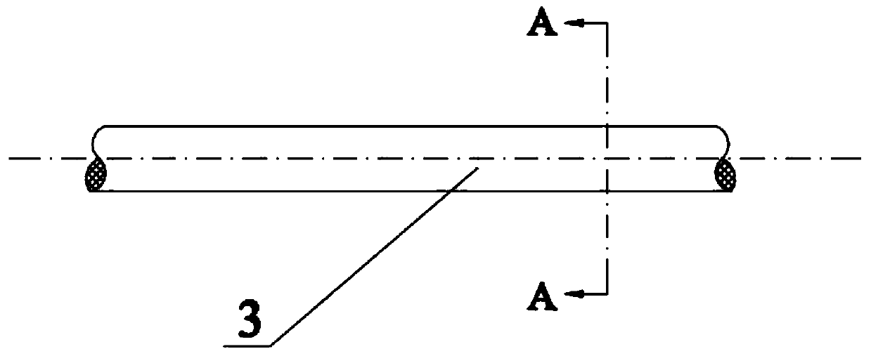
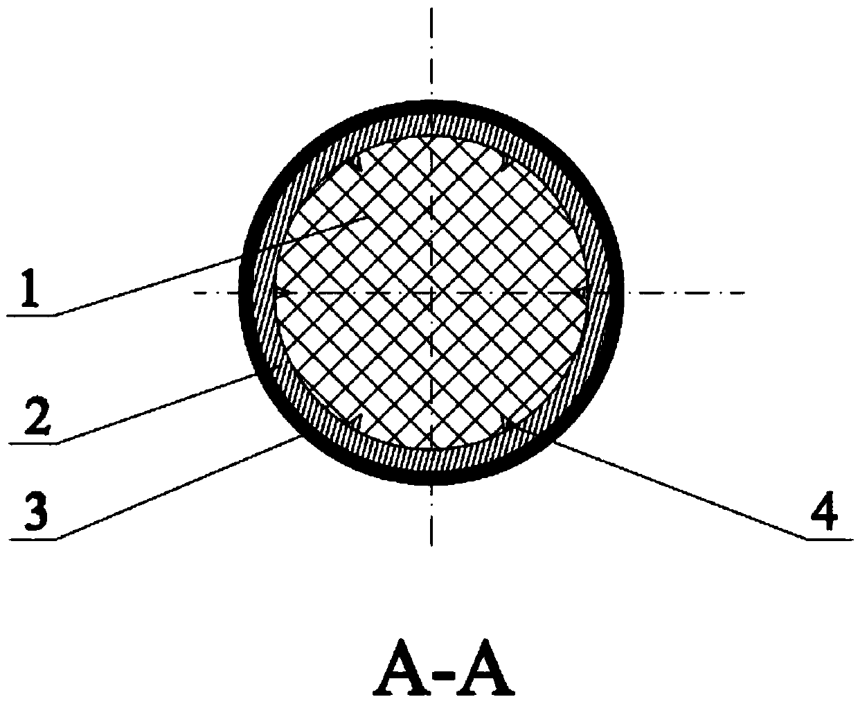
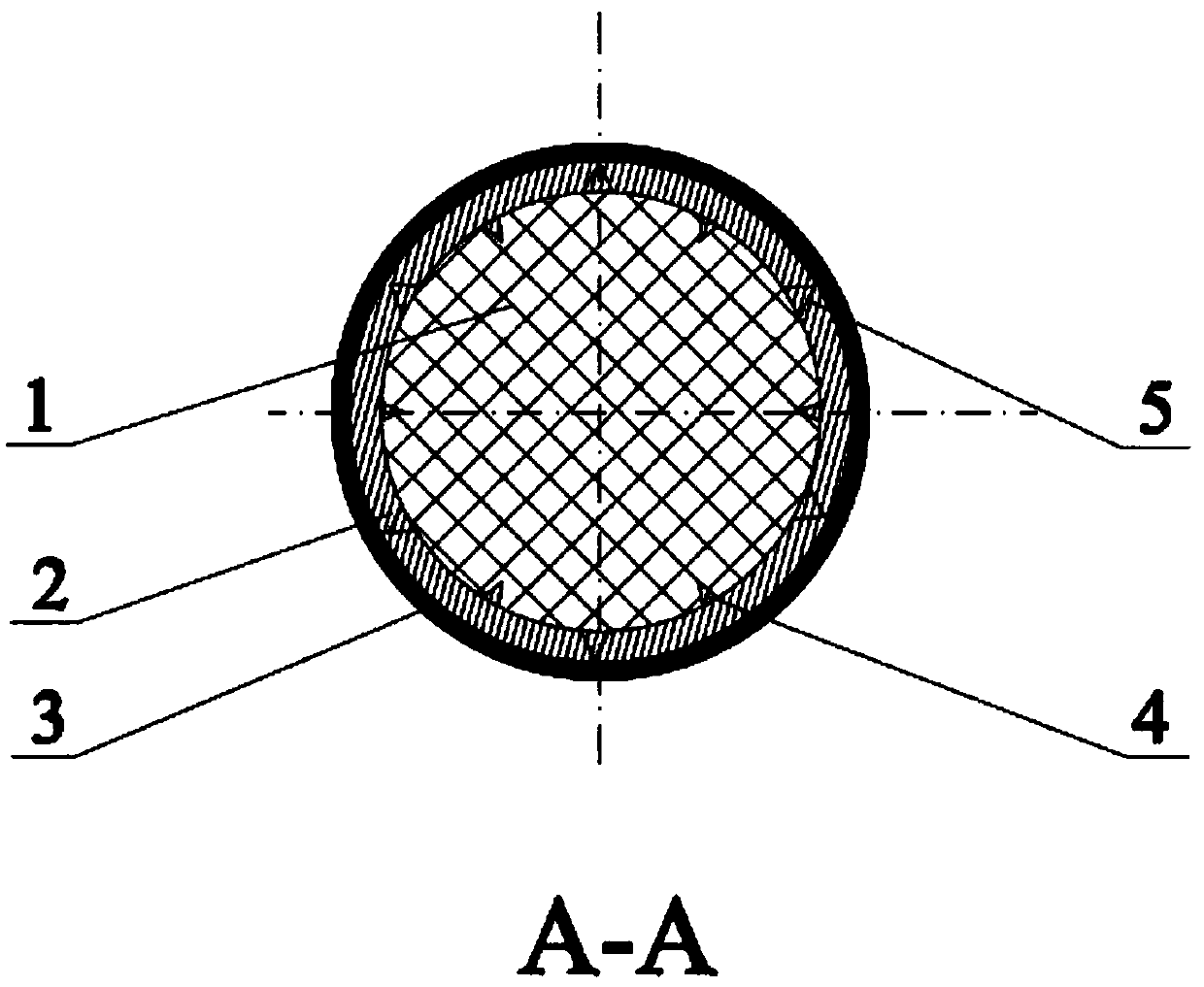
[0025] An ignition device for exothermic welding, comprising an ignition tube 2, an ignition core 1 and a heat insulation layer 3, the ignition core 1 is arranged in the ignition tube 2, and the ignition core 1 is gunpowder , the ignition tube 2 is any one of a round tube, a square tube, and a polygonal tube, the wall thickness of the ignition tube 2 is 5 to 40 in thickness ratio to the heat insulation layer 3, and the ignition tube 2 It is a magnesium tube, and the inner wall of the ignition tube 2 is provided with several protrusions 4, the bottom surface of the protrusions 4 is close to the inner wall of the ignition tube 2 and the central axis of the protrusion 4 is perpendicular to the The inner wall of the ignition tube 2, several of the protrusions 4 are evenly distributed on the inner wall of the ignition tube 2, the protrusions 4 are preferably conical, and the heat insulation layer 3 is arranged on the inner wall of the ignition tube 2. On the outer surface of the co...

Embodiment 2

[0027] As shown in the drawings, an ignition device for exothermic welding includes an ignition tube 2, an ignition core 1 and a heat insulation layer 3, and the ignition tube 2 is any one of a round tube, a square tube, and a polygonal tube. One, the ignition tube 2 is a magnesium tube, and the slit magnesium strip is first drawn into a semicircular tubular shape with a thickness of 10-20 μm and a width of 7.5-10 mm by using a drawing die, and the A nickel layer 3 is plated on the outer wall, with a thickness of 0.5-2 μm; and then the ignition core 1 is filled into the ignition tube 2, and a seam core-shaped ignition material is formed after preliminary drawing. Finally, the preliminarily drawn drug core igniter is processed through drawing dies with different inner diameters, and finally a drug core igniter with a diameter of 2.5 to 3 mm is formed;

[0028] The ratio of the wall thickness of the ignition tube 2 to the thickness of the heat insulation layer 3 is 5-40, the ign...


PUM

PropertyMeasurementUnit
melting pointaaaaaaaaaa

Abstract

The invention relates to an ignition device for heat-release welding. The ignition device comprises an ignition tube, an ignition core and a heat insulation layer, wherein the ignition core is arranged in the ignition tube; a plurality of bumps are arranged on the inner wall of the ignition tube; the bumps are uniformly distributed on the inner wall of the ignition tube; the bumps are in the shapes of circular cones; and the heat insulation layer is arranged on the outer surface of the ignition tube. An ignition agent only needs to ignite by a common lighter, and does not need to use equipmentsuch as an ignition gun, so that welding convenience is improved, and welding cost is reduced.

Description

technical field [0001] The invention relates to an exothermic welding ignition agent for grounding grid construction, in particular to an ignition device for exothermic welding. Background technique [0002] Exothermic welding is a new type of welding method that produces liquid high-temperature copper liquid and alumina residue through the chemical reaction (exothermic reaction) of copper oxide and aluminum, and uses the high temperature generated by the exothermic reaction to achieve high-performance electrical welding. It has been widely used in grounding systems such as power stations, substations, transmission and transformation line towers, and radars. At present, the exothermic welding construction technology is to cover the surface of the exothermic welding powder with pyrotechnic powder and the mold opening, and ignite the pyrotechnic powder through the ignition gun to cause the exothermic solder powder to burn to complete the welding. Pyrotechnic powder is flammab...

Claims


Application Information

Patent Timeline
Patent Type & Authority Applications(China)
IPC IPC(8): B23K23/00
CPCB23K23/00
Inventor 耿进锋王忠强汪毅庄清臣张留斌崔大田张健壮张元龙伟民钟素娟纠永涛时洪飞
Owner STATE GRID HENAN ELECTRIC POWER ELECTRIC POWER SCI RES INST
Learn More