
Automatic adjusting device and method for inhibiting cavitation of centrifugal pump

An automatic adjustment, centrifugal pump technology, applied in the components of the pumping device for elastic fluid, pump, pump control and other directions, can solve the problems of cavitation instability, etc. Effect

Active Publication Date: 2019-04-26
INST OF ENGINEERING THERMOPHYSICS - CHINESE ACAD OF SCI
View PDF0 Cites 5 Cited by
  • Summary
  • Abstract
  • Description
  • Claims
  • Application Information

AI Technical Summary

Problems solved by technology

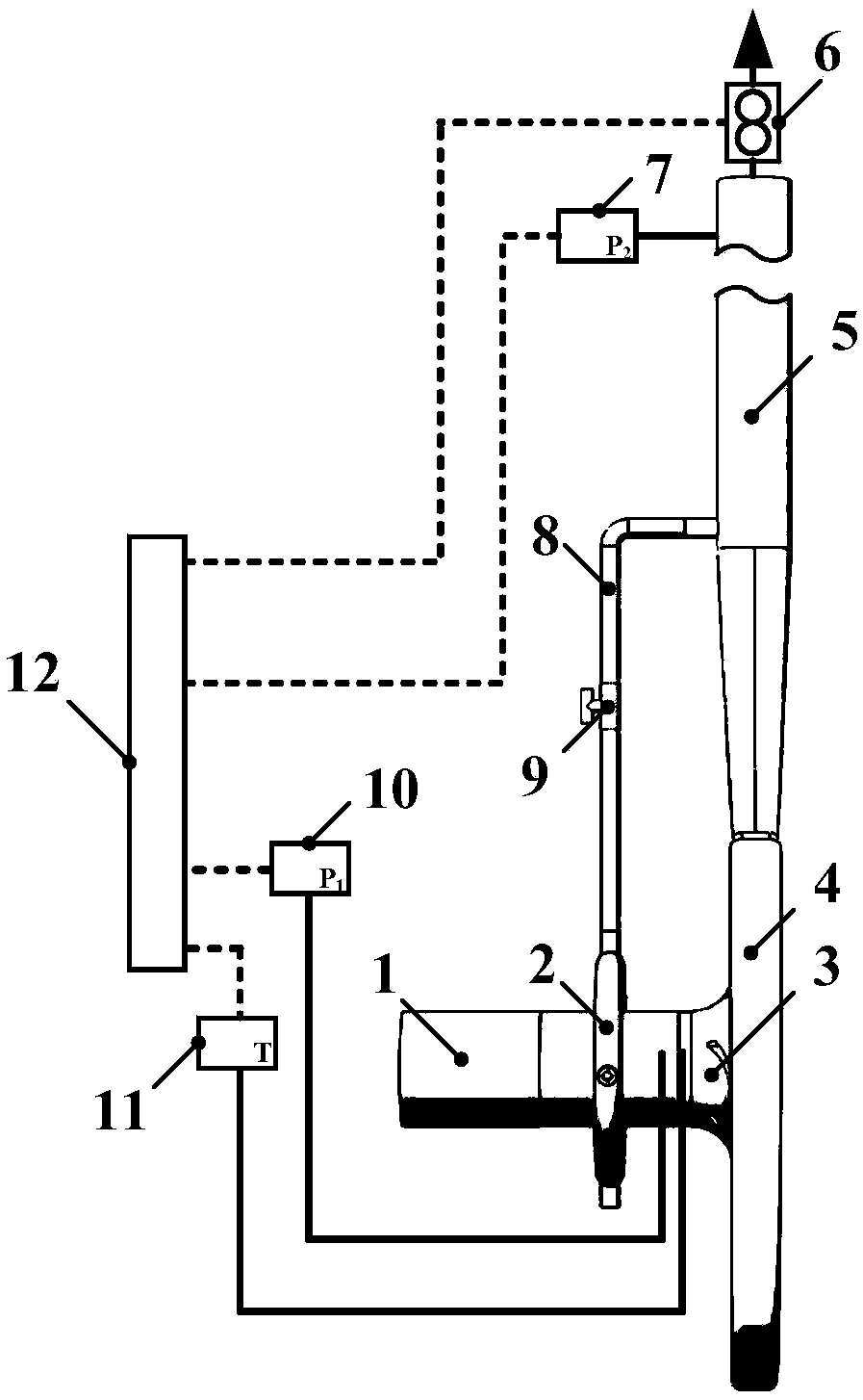
[0004] Aiming at the cavitation unstable operation problem of the existing centrifugal pump under different working conditions, the purpose of the present invention is to provide an automatic adjustment device and method for suppressing the cavitation of the centrifugal pump, by monitoring the working state of the centrifugal pump in real time, especially its progress The real-time monitoring of the outlet pressure and temperature information judges the cavitation state of the centrifugal pump. According to the demand, the high-pressure fluid is drained from the outlet pipe of the centrifugal pump to the inlet of the centrifugal pump, and can be automatically adjusted through the electric control valve installed on the liquid replenishment pipe to achieve Increase the inlet pressure of the centrifugal pump, improve and inhibit the occurrence of cavitation

Method used


Image

  • Automatic adjusting device and method for inhibiting cavitation of centrifugal pump
  • Automatic adjusting device and method for inhibiting cavitation of centrifugal pump

Examples


Embodiment Construction

[0029] In order to make the object, technical solution and advantages of the present invention clearer, the present invention will be further described in detail below with reference to the accompanying drawings and examples.

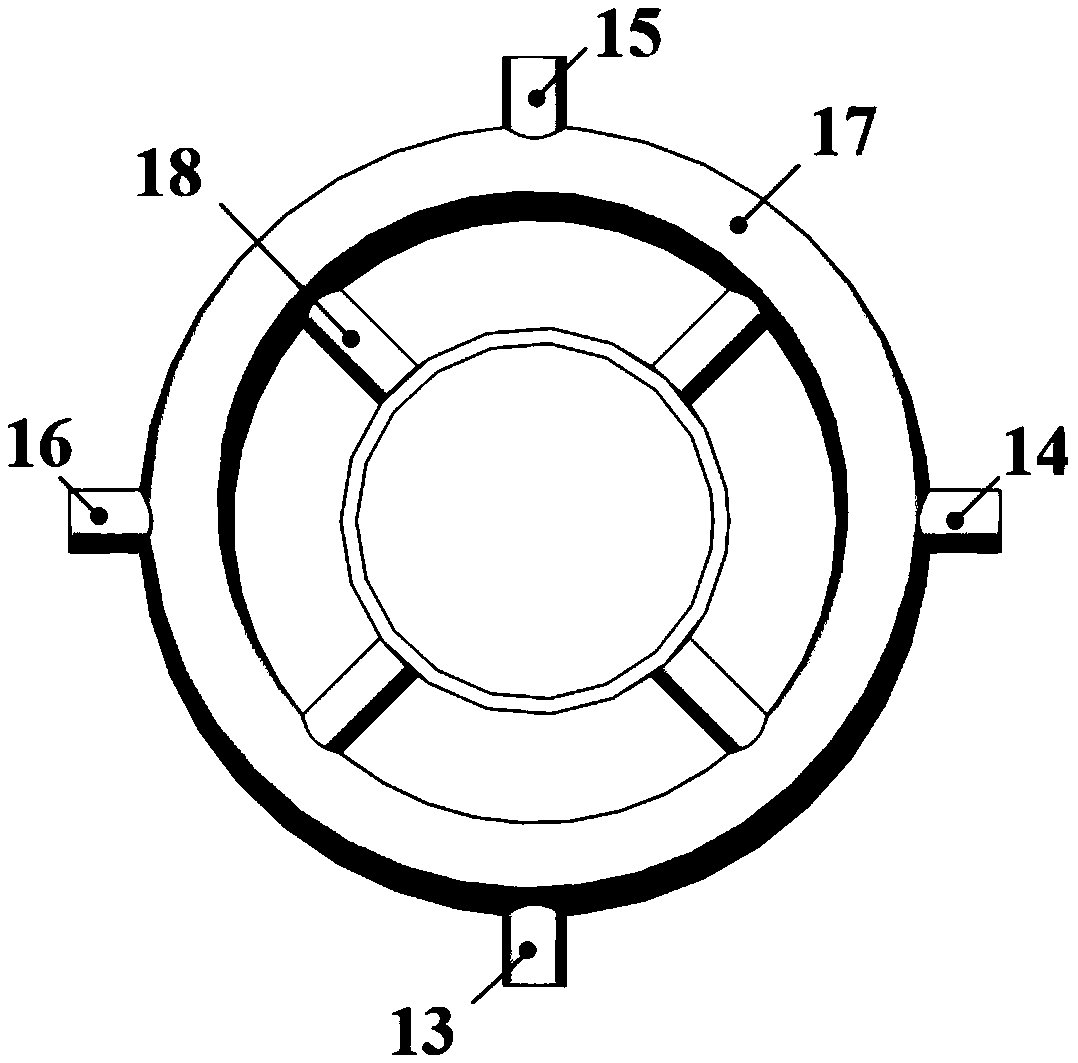
[0030] Such as figure 1 As shown, the automatic adjustment device for suppressing cavitation of a centrifugal pump of the present invention includes a centrifugal pump 3, the centrifugal pump 3 includes an inlet pipe 1 and an outlet pipe 2, and a valve with an electric regulating valve 9 is arranged between the inlet pipe 1 and the outlet pipe 2. The liquid replenishment pipe 8, the inlet of the liquid replenishment pipe 8 communicates with the outlet pipe 2, and an annular liquid replenisher 2 is sleeved on the inlet pipe 1. The annular liquid replenisher 2 includes a ring pipe 17 and is communicated with the ring pipe 17 and is evenly arranged in the ring along the circumferential direction. The four branch pipes 18 inside the pipe 17, the outlets of ...


PUM


Abstract

The invention discloses an automatic adjusting device and method for inhibiting cavitation of a centrifugal pump. The cavitation state of the centrifugal pump is judged in real time by monitoring theflow, the inlet and outlet pressure and the inlet temperature of the centrifugal pump in real time, a control unit calculates the device net positive suction head NPSHa and the required net positive suction head NPSHr through the temperature and the inlet pressure, and if NPSHa is smaller than or equal to NPSHr, an electric control valve is controlled to be continuously opened and stops acting till NPSHa is larger than NPSHr. High-pressure fluid is guided to a centrifugal pump inlet on a centrifugal pump outlet pipe according to the requirement, automatic adjustment can be achieved through theelectric control valve arranged on a liquid supplementing pipe, and the effects of increasing the centrifugal pump inlet pressure and improving and inhibiting cavitation are achieved. According to the automatic adjusting device and method for inhibiting cavitation of the centrifugal pump, different working condition requirements can be effectively met for automatic adjustment and inhibition on cavitation, the stable running range of the centrifugal pump is greatly widened, the cavitation state of the centrifugal pump can be effectively improved, and the wide application value is achieved.

Description

technical field [0001] The invention belongs to the cavitation performance adjustment and suppression technology in the field of fluid machinery, and relates to an automatic adjustment device and method for suppressing cavitation of a centrifugal pump, which can promote self-control and adjustment under cavitation conditions to realize cavitation suppression of a centrifugal pump occurrence of the phenomenon. Background technique [0002] Cavitation in fluid machinery is a common and serious phenomenon, and it is also one of the important reasons for the unstable operation of hydraulic machinery. Unstable cavitation flow will destroy the stable flow field in the centrifugal pump, and the wall material will be denuded, causing a series of problems such as vibration and noise. In severe cases, it will damage the flow-passing parts and cause the machine to fail. With the development of industry, such as the field of supercritical compressed air energy storage, higher and highe...

Claims


Application Information

Patent Timeline
IPC IPC(8): F04D29/66F04D15/00
CPCF04D15/00F04D29/669
Inventor 侯虎灿左志涛周鑫郭文宾李文陈海生
Owner INST OF ENGINEERING THERMOPHYSICS - CHINESE ACAD OF SCI
Learn More