Output rapid chaining mechanism and speed reducer

A technology of output mechanism and reducer, applied in mechanical equipment, belt/chain/gear, transmission parts, etc., can solve the problems of damage to reducer, coaxiality error, long coupling installation time, etc.

Inactive Publication Date: 2019-04-26
湖北斯微特传动有限公司
View PDF7 Cites 3 Cited by
  • Summary
  • Abstract
  • Description
  • Claims
  • Application Information

AI Technical Summary

Problems solved by technology

[0004] The main purpose of the present invention is to provide an output quick link mechanism and reducer, which can sol

Method used


Image

  • Output rapid chaining mechanism and speed reducer
  • Output rapid chaining mechanism and speed reducer
  • Output rapid chaining mechanism and speed reducer

Examples


Embodiment 2

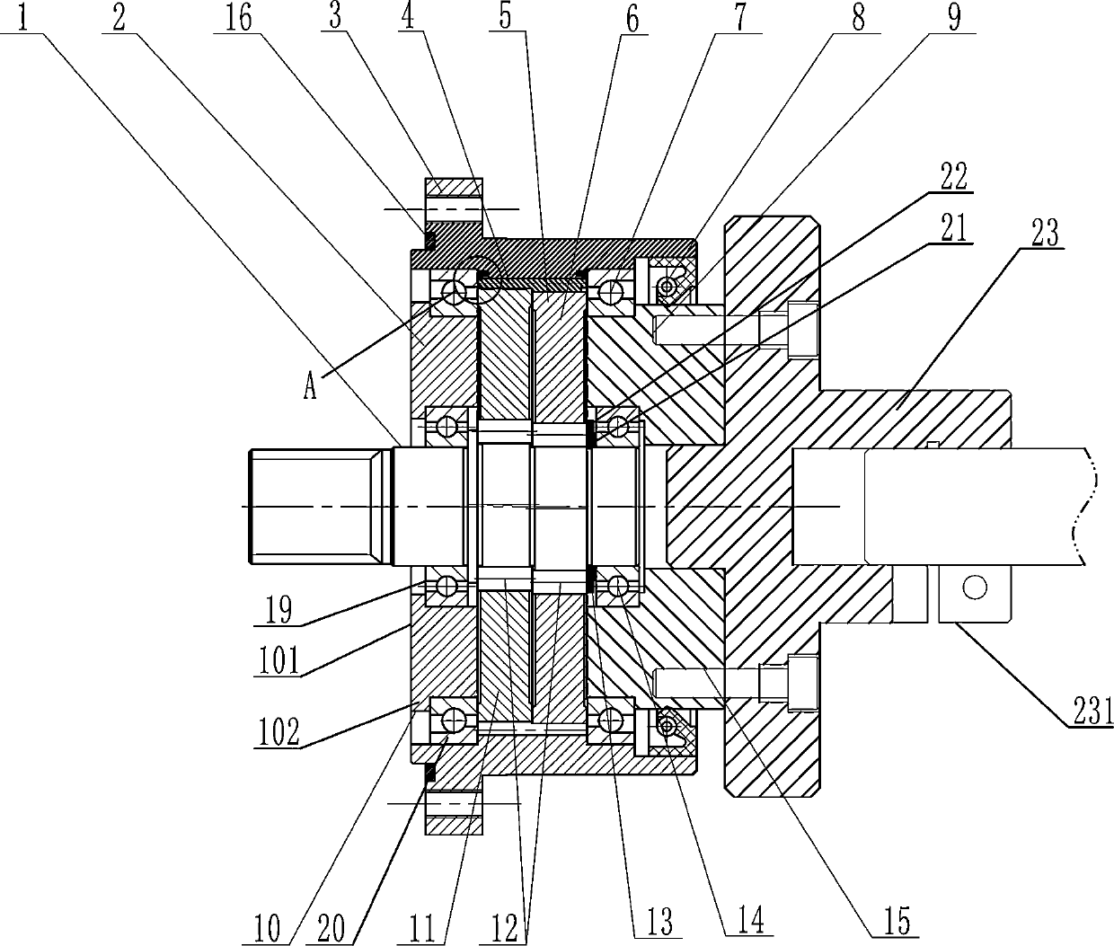
[0052] In combination with Embodiment 1, the installation method of the pin tooth positioning flange includes:

[0053] 1) Install one of the needle-tooth positioning flanges 24, install the positioning pin 25 on the positioning groove 31 inside the housing 3, and align the flange positioning groove 241 of the needle-tooth positioning flange 24 with the positioning pin 25 on the positioning groove 31 Cooperate to position the pin-tooth positioning flange 24, which plays the role of positioning and also plays the role of anti-rotation;

[0054] 2) After positioning, carry out cold fitting of the pin tooth positioning flange 24. After the installation is completed, install the pin tooth pin 4, cycloidal wheel 5, output seat 9 and input shaft 1. After the installation, install the second pin tooth Locate the flange 24, the installation method is the same as above, and the installation sequence prevents the problem that the cycloidal wheel 5 cannot be installed during installation...


PUM


Abstract

The invention discloses an output rapid chaining mechanism and speed reducer. A shell, an output base and an input shaft are included. The input shaft is provided with an eccentric wheel, and the eccentric wheel is connected with cycloidal gears through crank bearings. A plurality of gear pins are arranged on the inner wall of the shell along the circumference. The gear pins are intermittently engaged with the cycloidal gears. A positioning flange is arranged at the outer end of the output base. A positioning cylinder is arranged at one end of the positioning flange and arranged in an inner hole of the output base for inner hole positioning. A shaft fastening component is arranged at the other end of the positioning flange, the shaft fastening component and the positioning flange are of anintegrated structure, a crack is arranged between the positioning flange and the shaft fastening component, and shaft connection can be rapidly conducted. The problems that the traditional coupler installing time is long, and during installation, debugging is needed are solved.

Description

technical field [0001] The invention relates to a reducer, in particular to an output quick link mechanism and a reducer. Background technique [0002] Pin-toothed cycloidal reducers have been widely used as transmission devices for industrial robots. Because the cycloidal pin gear reducer adopts a planetary transmission structure with less tooth difference, it has the advantages of small size, light weight, large transmission ratio range, stable operation and strong bearing capacity, etc., but the structure of the general pin gear cycloidal reducer is complex . [0003] At present, the output end of the pin tooth cycloid reducer generally adopts flange connection and shaft connection, and the flange connection generally uses a coupling to connect the external shaft, but when the general coupling is used, if The occurrence of two-axis eccentricity will cause additional load in the coupling, damage the coupling and reducer, and the installation time is longer, and the requi...

Claims


Application Information

Patent Timeline
IPC IPC(8): F16H1/32F16H57/021F16H57/022F16H57/023F16H57/08
CPCF16H1/32F16H57/021F16H57/022F16H57/023F16H57/08F16H2057/0221
Inventor 董红刚余运清程志毅
Owner 湖北斯微特传动有限公司
Why Eureka
Try Eureka