A vacuum drying device for powder metallurgy

A vacuum drying device and powder metallurgy technology, which is used in drying cargo handling, drying solid materials, drying solid materials without heating, etc. Uniform distribution and drying efficiency, increase the convective heat transfer coefficient, and avoid the effect of condensed liquid droplets

Active Publication Date: 2019-06-21
长沙微纳坤宸新材料有限公司 +1
View PDF7 Cites 0 Cited by
  • Summary
  • Abstract
  • Description
  • Claims
  • Application Information

AI Technical Summary

Problems solved by technology

In powder metallurgy technology, in order to improve the performance of metal powder, it is necessary to carry out flexible coating modification on the surface of the powder. After modification, it is necessary to evaporate the liquid in the powder suspension to obtain a surface-modified high-purity solid powder. In order to obtain a powder with low oxygen content, uniform particle size, and good flexible coating effect of organic matter, the drying rate and the uniformity of suspension distribution during drying are two extremely important factors. If the drying rate is slow and the drying time is too long, it is easy to cause The decomposition, coking and embrittlement of the flexible organic forming agent will also lead to the oxidation of the powder. If the suspension is unevenly distributed during drying, it will not be possible to obtain a powder coated with organic matter, which will seriously affect the effect of powder modification.
[0003] The existing vacuum drying equipment for powder metallurgy adopts electric heating mechanism for heating, and the solid-liquid mixture is heated unevenly. Although the evaporation rate of the liquid is fast, the rate of gas extraction and condensation is slow, and the overall drying rate is limited. As a result, the drying time is too long, the flexible organic forming agent is decomposed, coked and brittle, and the flexible coating cannot be obtained. In addition, the existing vacuum drying equipment mainly exhausts the gas through vacuuming, which is not only inefficient, but also when the steam encounters Condensation on the wall of the top cover of the container will also drip back into the suspension. When the condensate drips back, it will also cause local oscillation of the suspension, resulting in uneven distribution of the suspension, resulting in the inability to obtain a uniform coating layer. Therefore, the existing vacuum The drying device cannot meet the efficient, fast and clean drying requirements required for powder surface modification in the powder metallurgy industry, and cannot realize the modification process of uniform flexible organic coating on the powder surface, which restricts the further development of powder metallurgy technology

Method used


Image

  • A vacuum drying device for powder metallurgy
  • A vacuum drying device for powder metallurgy
  • A vacuum drying device for powder metallurgy

Examples


Embodiment 1

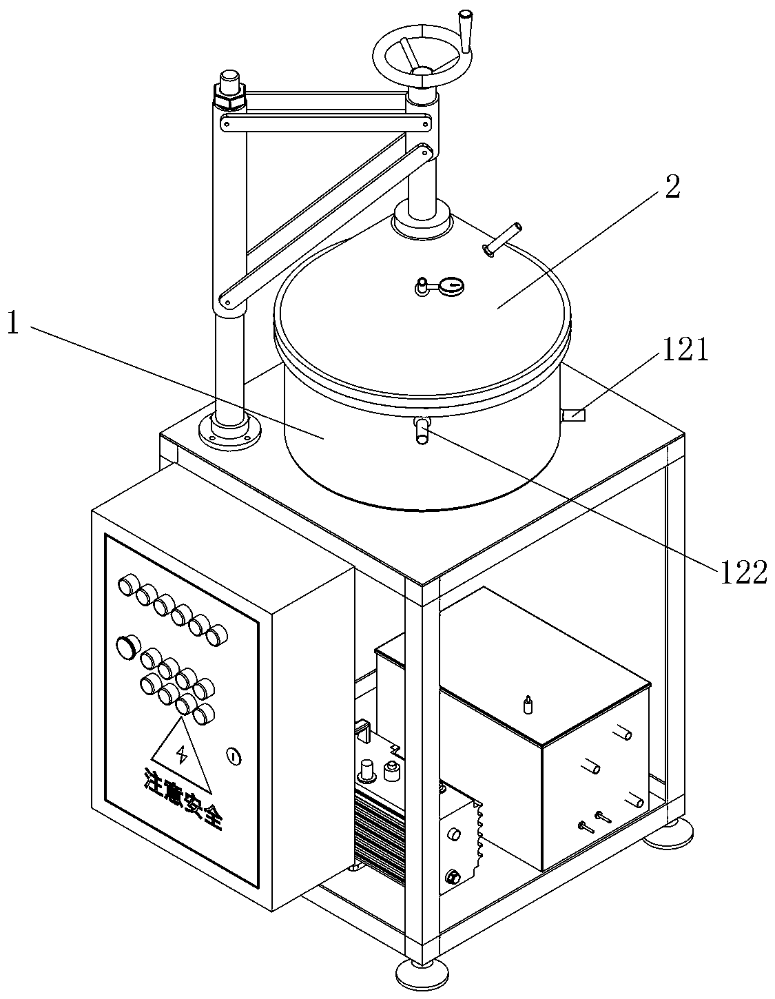
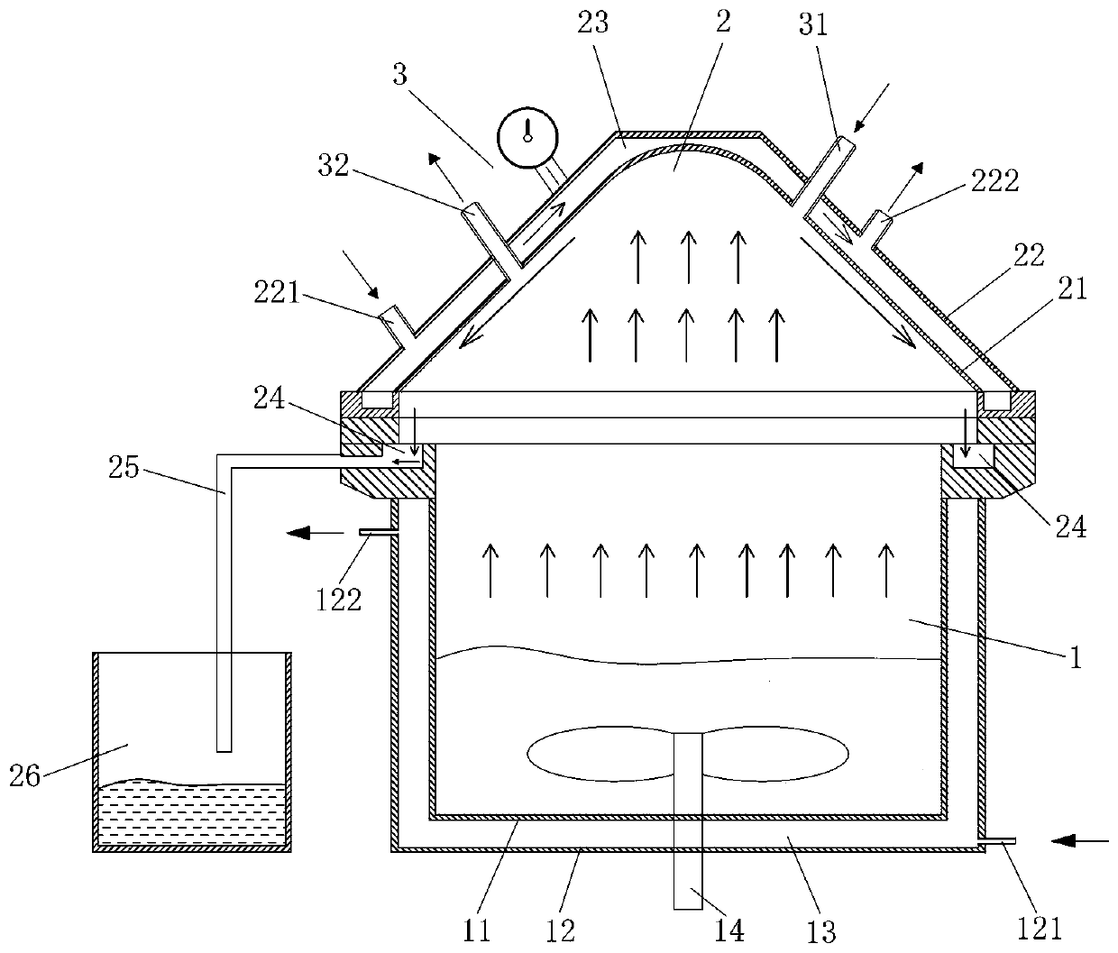
[0038] Such as Figure 1 to Figure 6 As shown, the vacuum drying device for powder metallurgy in this embodiment includes a cylinder body 1 and a top cover 2 for condensing and guiding the steam out. The cylinder body 1 and the top cover 2 are hermetically connected to form a closed cavity . Specifically, the connection between the cylinder body 1 and the top cover 2 is connected by a sealing flange to ensure good airtightness of the device as a whole. By inducing the rapid condensation and discharge of steam at the top cover, the drying efficiency and quality are greatly improved.

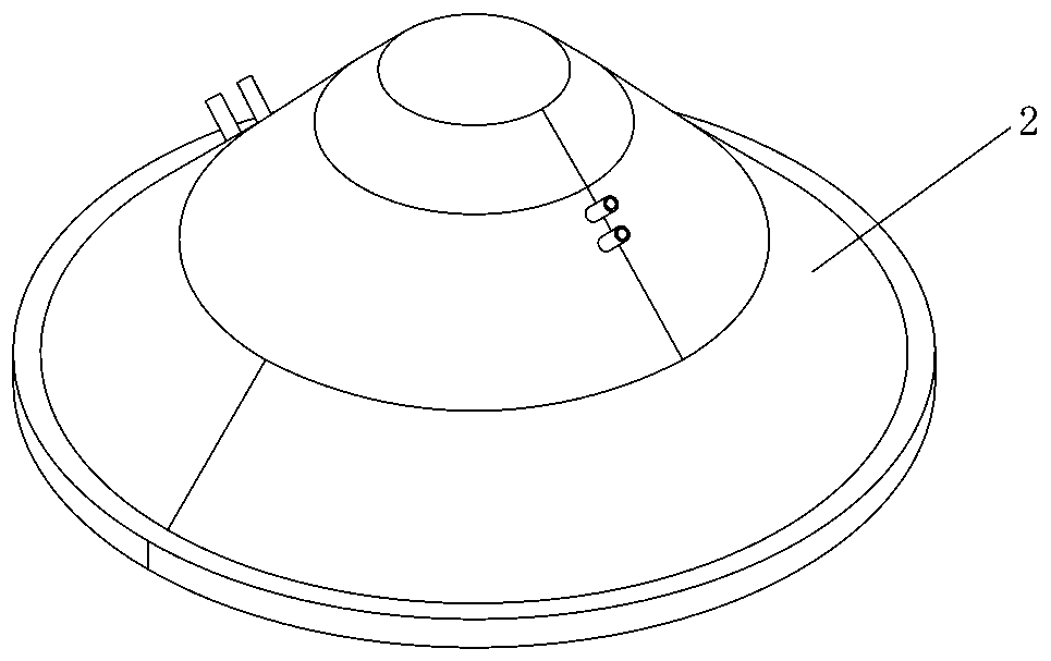
[0039] In this embodiment, the top cover 2 includes a top cover inner wall 21, a top cover outer wall 22, and a cooling medium circulation channel 23 interlayered between the top cover inner wall 21 and the top cover outer wall 22, and a cooling medium inlet 221 is opened on the top cover outer wall 22. And the cooling medium outlet 222 , the cooling medium inlet 221 and the cooling medium outle...

Embodiment 2

[0056] The vacuum drying device of this embodiment is basically the same as that of Embodiment 1, the main difference is that: in this embodiment, the inner wall 21 of the top cover is in the shape of a spherical surface with the middle protruding upward.

[0057] In this embodiment, the diameter of the bottom of the top cover 2 is 800 mm, and the angle α between the wall surface of the top cover inner wall 21 and the horizontal plane is 46°.

[0058] In this embodiment, the included angle β between the line connecting the cross-section points adjacent to and located on both sides of the top cover 2 and the horizontal plane is 2.5°.

[0059] In this embodiment, the depth h of the arc-shaped inner concave surface on the upper surface of the diversion groove 211 is 2.5mm, the width w of the arc-shaped inner concave surface is 6mm, and the cooling medium between the top cover inner wall 21 and the top cover outer wall 22 The circulation channel 23 has a thickness of 23mm.

[006...

Embodiment 3

[0063] The vacuum drying device of this embodiment is basically the same as that of Embodiment 1, the main difference being that: in this embodiment, the inside of the diversion groove 211 is a hollow structure, and the inner cavity of the diversion groove 211 is connected with the cooling mechanism on the top cover 2. The medium circulation channel 23 is connected.

[0064] In this embodiment, the axis of the cooling medium inlet 221 coincides with the tangent of the inner cavity of the guide groove 211 at the bottom.

[0065] In this embodiment, the diameter of the bottom of the top cover 2 is 650 mm, and the angle α between the inner wall 21 of the top cover and the horizontal plane is 45.5°.

[0066] In this embodiment, the included angle β between the connecting line between the adjacent cross-section points located on both sides of the top cover 2 and the horizontal plane is 2.3°.

[0067] In this embodiment, the depth h of the circular arc-shaped inner concave surface ...


PUM


Abstract

The invention discloses a vacuum drying device for powder metallurgy. The vacuum drying device comprises a cylinder and further comprises a top cover, wherein the top cover is used for condensing steam as well as draining and exhausting steam condensate; the cylinder and the top cover are connected in a sealing manner so as to form a closed cavity; the top cover comprises a top cover inner wall, atop cover outer wall and a cooling medium circulation channel; the cooling medium circulation channel is positioned on an interlayer between the top cover inner wall and the top cover outer wall; thetop cover inner wall takes the shape of a cone or a sphere of which the middle protrudes upward; a cooling medium inlet and a cooling medium outlet are formed on the top cover outer wall and both communicate with the cooling medium circulation channel; a condensate collecting tank used for collecting the steam condensate is arranged below the edge of the top cover inner wall; a pipeline used forexhausting the steam condensate in the condensate collecting tank is connected onto the condensate collecting tank; and a recycling barrel is connected with the output end of the pipeline. The vacuumdrying device disclosed by the invention has the advantages that the drying efficiency is high, the liquid residue is low, the rapid batched drying process can be achieved, and the purity and the quality of powder obtained from the drying process are high.

Description

technical field [0001] The invention belongs to the technical field of powder metallurgy, in particular to a vacuum drying device used for coating and modifying the surface of powder in powder metallurgy. Background technique [0002] Powder metallurgy is an important part of modern industrial development, especially in many special metals, ceramic materials and parts manufacturing industries, powder metallurgy has an irreplaceable position. In powder metallurgy technology, in order to improve the performance of metal powder, it is necessary to carry out flexible coating modification on the surface of the powder. After modification, it is necessary to evaporate the liquid in the powder suspension to obtain a surface-modified high-purity solid powder. In order to obtain a powder with low oxygen content, uniform particle size, and good flexible coating effect of organic matter, the drying rate and the uniformity of suspension distribution during drying are two extremely import...

Claims


Application Information

Patent Timeline
Patent Type & Authority Patents(China)
IPC IPC(8): F26B5/04F26B25/00
CPCF26B5/005F26B5/041F26B25/003
Inventor 范景莲成创功雷左明李鹏飞田家敏刘涛范衍吕永齐
Owner 长沙微纳坤宸新材料有限公司
Why Eureka
Try Eureka