Labeling machine

A labeling machine and labeling technology, applied in the direction of labeling machines, labels, conveyor objects, etc., can solve the problems of slow running speed, non-adjustable height of label printers, and easy noise generation

Inactive Publication Date: 2019-04-30
石家庄泽厚科技有限公司
View PDF10 Cites 0 Cited by
  • Summary
  • Abstract
  • Description
  • Claims
  • Application Information

AI Technical Summary

Problems solved by technology

The above existing technologies have technical deficiencies such as complex mechanical structure and inconvenient lubrication, increased wear after long-term use, easy to generate noise, and great inconvenience to later maintenance.
[0006] The main structure of the labeling mechanism is to clamp the blood collection test tube by the fixed driving roller and the moving roller moving opposite to the driving roller, and the label printing of the clamped blood collection test tube is completed by the label printer. The main problems are: The moving frame driven by the electromagnetic device and equipped with the moving roller is guided and matched along the slideway that fits with the gap. In addition to affecting the clamping effect between the driving roller and the moving roller, there are problems of poor transmission flexibility and low precision. Long-term wear is more likely to lead to the aggravation of the above phenomenon; second, the electromagnetic coil lacks heat dissipation settings, and long-term operation of the electromagnetic coil will generate heat; third, the height of the label printer cannot be adjusted, resulting in restrictions on the label printing position of the blood collection test tube
The above-mentioned existing products are driven by a ball screw structure in the longitudinal drive of the cross slide table. The running speed of the above-mentioned structure is relatively slow, and there are technical deficiencies such as slow overall working speed and low working efficiency of the labeling machine equipment.

Method used


Image

  • Labeling machine
  • Labeling machine
  • Labeling machine

Examples


Embodiment Construction

[0085] The present invention will be further described below in conjunction with the examples, but it should not be interpreted as a limitation of the present invention. The protection scope of the present invention is based on the contents recorded in the claims. protection scope of the present invention.

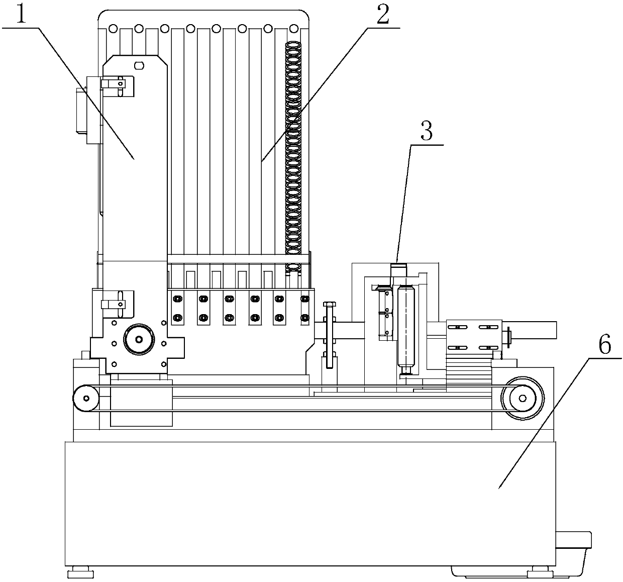
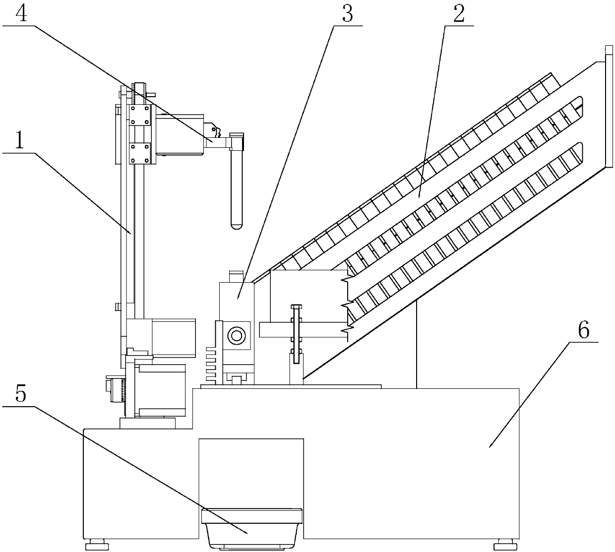
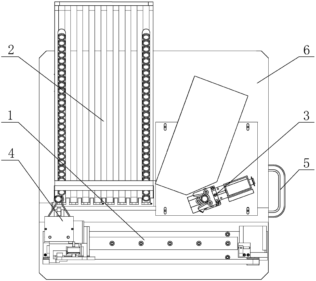
[0086] The overall structure of this embodiment and the structure of each corresponding mechanism are as shown in the figure, including a cross slide 1, a silo mechanism 2, a labeling mechanism 3, a manipulator and a receiving box 5, and the manipulator grabs blood under the control of the central control device After the test tube is transported to the labeling mechanism 3 through the cross slide 1, the blood collection test tube after labeling falls into the material receiving box 5; the manipulator is an electromagnetic manipulator 4, which includes two oppositely arranged mechanical grippers 4a , the grasping parts of the front ends of the two mechanical grippers 4a ar...


PUM


Abstract

The invention belongs to labeling devices, and especially relates to a labeling machine. The machine includes a cross-shaped slide table, a material cabin mechanism, a labeling mechanism, a manipulator and a material receiving box; the manipulator can convey a blood sampling test tube to the labeling mechanism through the cross-shaped slide table after grabbing the blood sampling test tube under the controlling of a central control device, so that the labelled blood sampling test tube can fall into the material receiving box; the manipulator selects an electromagnetic manipulator and incudes two mechanical clamping hands in opposite arrangement; grabbing parts on the front ends of the two mechanical clamping hands can fit with the profile of the blood sampling test tube, and the rear endsof the mechanical clamping hands are in rotatory assembling with rotating shafts; the mechanical clamping hands can be controlled by a power input device to do opposite or reverse rotation so that thegrabbing or loosening of the blood sampling test tube can be realized; and the power input device includes an electromagnet arranged between the middle parts of the two mechanical clamping hands andreset springs connected between the two mechanical clamping hands. Thus, technical problems in the prior art of low work efficiency, complex structure and poor universality can be effectively solved,and therefore, the machine has advantages of being high in working efficiency, compact in structure and good in adaptability.

Description

technical field [0001] The invention belongs to a labeling device, in particular to a labeling machine. Background technique [0002] Blood test is a common detection method used in clinical diagnosis in hospitals at present, and blood collection test tube is an essential device used in the above detection. At present, most of the blood collection test tubes in hospitals are obtained by manually printing and labeling the test tubes with prefabricated barcodes. In the above-mentioned prior art, manual labeling requires the hospital to be equipped with a large number of staff, and this working method itself has the disadvantages of manual labeling. Poor label position consistency, error-prone, and barcode unavoidable technical defects such as repeated codes and loss, seriously affect the accuracy of blood collection information. [0003] As a special equipment, the automatic labeling machine is currently used by a few hospitals. The working principle of the automatic labeling...

Claims


Application Information

Patent Timeline
Patent Type & Authority Applications(China)
IPC IPC(8): B65C9/02B65C9/06B65C9/46B65G47/90
CPCB65C9/02B65C9/06B65C9/46B65G47/90
Inventor 不公告发明人
Owner 石家庄泽厚科技有限公司
Why Eureka
Try Eureka