

Solar cell turning mechanism
A technology of solar cells and flip mechanism, applied in circuits, photovoltaic power generation, electrical components, etc., can solve problems such as low work efficiency, adsorption failure, battery damage, etc., to achieve good flip, prevent damage, and prevent damage.
- Summary
- Abstract
- Description
- Claims
- Application Information
AI Technical Summary
Problems solved by technology
Method used
Image

Examples
Embodiment Construction
[0028] The following will clearly and completely describe the technical solutions in the embodiments of the present invention with reference to the accompanying drawings in the embodiments of the present invention. Obviously, the described embodiments are only some, not all, embodiments of the present invention. Based on the embodiments of the present invention, all other embodiments obtained by persons of ordinary skill in the art without making creative efforts belong to the protection scope of the present invention.
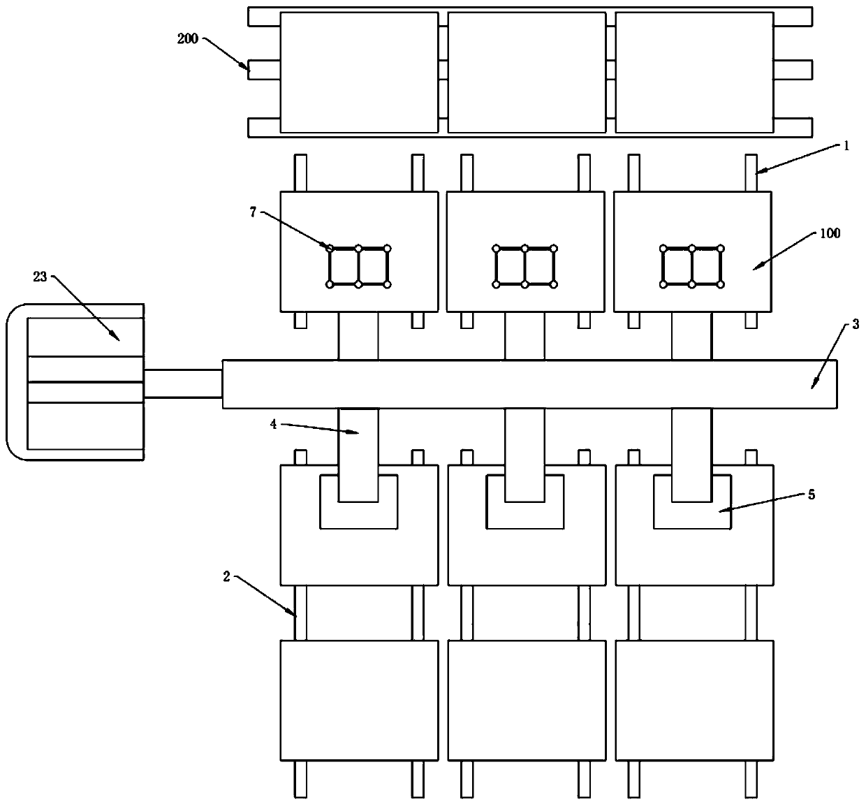
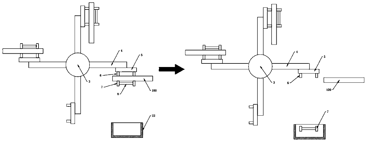
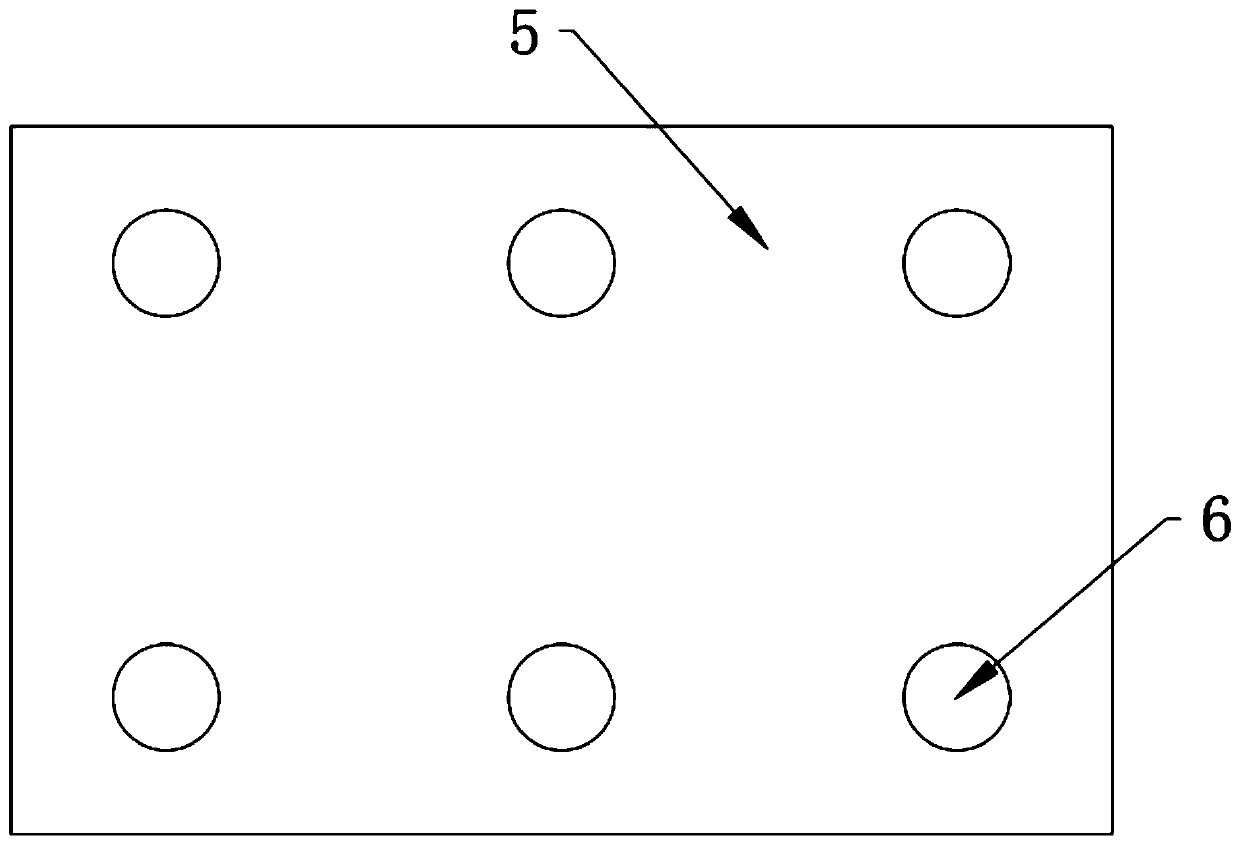
[0029] see Figure 1-9 , the present invention provides a technical solution:
[0030] A solar cell flipping mechanism, including a front conveyor belt 1 and a rear conveyor belt 2 which are separately arranged. Separate belts with gaps are used, so that the gaps between the individual belts can be used to place the subsequent fixing plate 5, and make the fixing plate 5 available for work. A rotating shaft is arranged between the front conveyor belt 1 and the...
PUM
 Abstract
Description
Claims
Application Information