A joint structure and construction method of section steel wrapped concrete columns and steel beams

A technology of concrete column and node structure, applied in building construction, construction and other directions, can solve the problems of low assembly process efficiency, inconvenient welding assembly, unfavorable construction speed and quality, etc. The effect of construction speed and quality improvement

Active Publication Date: 2020-07-14
HUBEI HUICHUANG HEAVY ENG
View PDF5 Cites 0 Cited by
  • Summary
  • Abstract
  • Description
  • Claims
  • Application Information

AI Technical Summary

Problems solved by technology

[0003] The current joint structure of concrete columns and steel beams needs to be installed on site in the actual construction area, which is not convenient for factory welding and assembly in advance, and the efficiency of the assembly process is low, which is not conducive to improving the construction speed and quality. Partially wrapped concrete column and steel beam joint structure and construction method to solve the above technical problems

Method used


Image

  • A joint structure and construction method of section steel wrapped concrete columns and steel beams
  • A joint structure and construction method of section steel wrapped concrete columns and steel beams

Examples


Embodiment 1

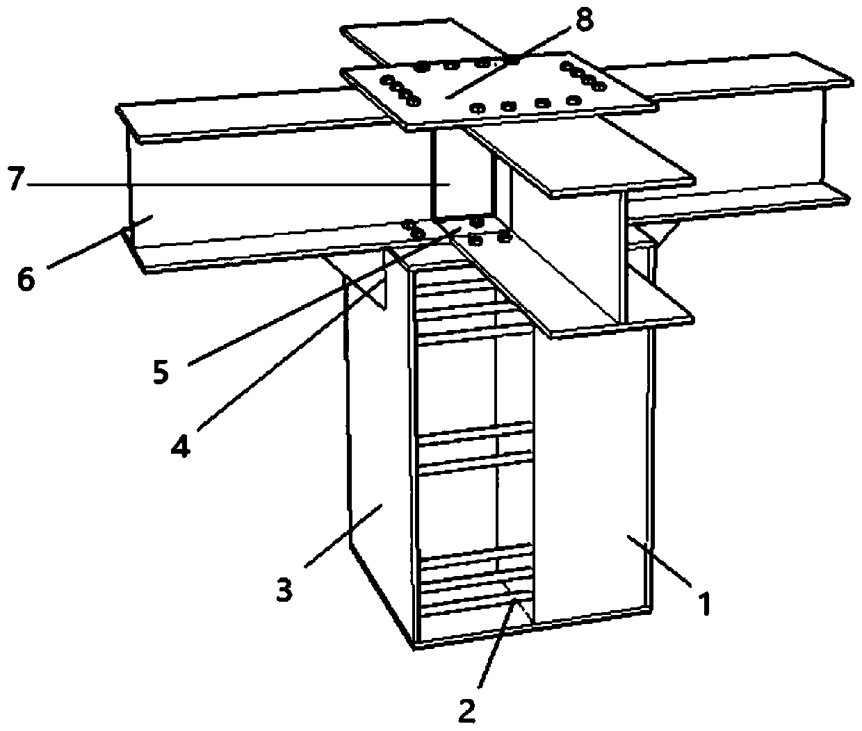
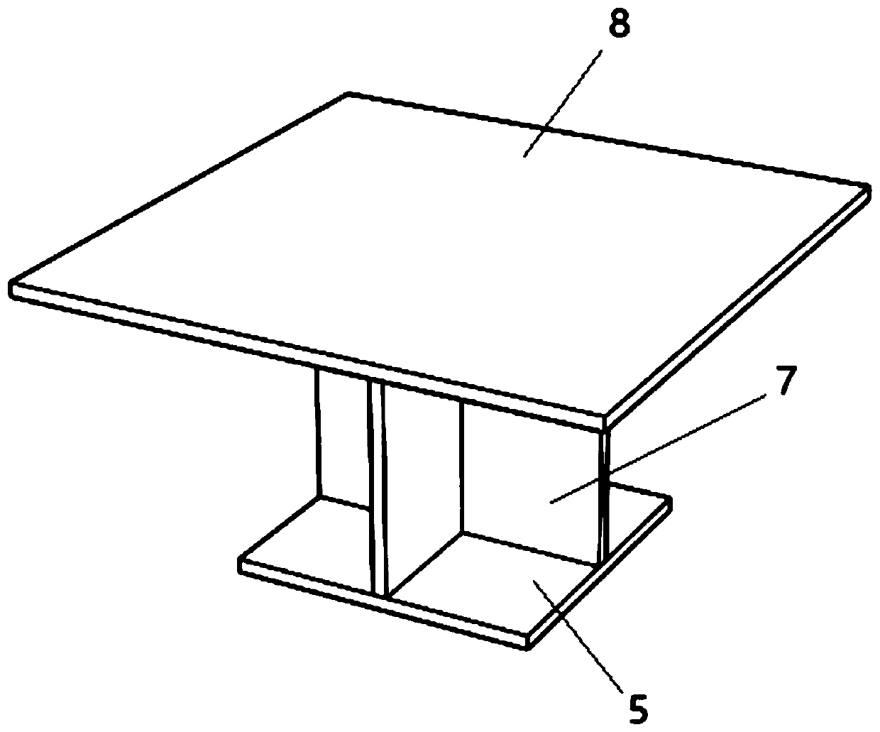
[0027] see Figure 1-2 , a joint structure of concrete columns and steel beams partially wrapped by section steel, including closed H-shaped steel 3, recycled concrete 1 is poured inside the closed H-shaped steel 3, a cross-shaped steel frame 7 is arranged on the closed H-shaped steel 3, and the cross-shaped steel An upper steel plate 8 and a lower steel plate 5 are respectively horizontally fixed on the upper and lower bottom of the frame 7, the lower steel plate 5 is fixed on the closed H-shaped steel 3, and the cross-shaped steel frame 7 is evenly provided with four steel plates fixedly connected with the lower steel plate 5 and the upper steel plate 8. I-beam 6.

[0028] In order to improve the structural strength of the connection between the I-beam 6 and the closed H-shaped steel 3 , a corbel 4 is welded and fixed between the I-beam 6 and the closed H-shaped steel 3 .

[0029] In order to ensure the supporting strength of the closed H-shaped steel 3, the upper and lower...

Embodiment 2

[0031] A construction method for a joint structure of concrete columns and steel beams partially wrapped by section steel, specifically comprising the following steps:

[0032] Step 1, welding and fixing the circular cross-section transverse steel rod 2 in the closed H-shaped steel 3;

[0033] Step 2: Center and level the four I-beams 6 on the upper end of the closed H-shaped steel 3. The extension direction of the four I-beams 6 corresponds to the direction of the four side walls of the closed H-shaped steel 3. The I-beams 6 pass through the bolts. Locked and connected to the upper steel plate of the closed H-beam 3;

[0034] Step 3, placing the cross-shaped steel frame 7 on the closed H-shaped steel 3, and fixing the cross-shaped steel frame 7 and the top of the closed H-shaped steel 3 through bolts;

[0035] Step 4. Weld and fix the upper steel plate 8 and the lower steel plate 5 to the top and bottom of the cross-shaped steel frame 7 respectively. The area of ​​the lower ...

Embodiment 3

[0040] A construction method for a joint structure of concrete columns and steel beams partially wrapped by section steel, specifically comprising the following steps:

[0041] Step 1, welding and fixing the circular cross-section transverse steel rod 2 in the closed H-shaped steel 3;

[0042] Step 2: Center and level the four I-beams 6 on the upper end of the closed H-shaped steel 3. The extension direction of the four I-beams 6 corresponds to the direction of the four side walls of the closed H-shaped steel 3. The I-beams 6 pass through the bolts. Locked and connected to the upper steel plate of the closed H-beam 3;

[0043] Step 3, placing the cross-shaped steel frame 7 on the closed H-shaped steel 3, and fixing the cross-shaped steel frame 7 and the top of the closed H-shaped steel 3 through bolts;

[0044] Step 4. Weld and fix the upper steel plate 8 and the lower steel plate 5 to the top and bottom of the cross-shaped steel frame 7 respectively. The area of ​​the lower ...


PUM


Abstract

The invention relates to a section steel partially wrapped concrete column and steel beam joint structure and a construction method thereof, and relates to the technical field of structural engineering. The section steel partially wrapped concrete column and steel beam joint structure comprises closed H-shaped steel, recycled concrete is poured in the closed H-shaped steel, and a cross-shaped steel frame is arranged on the closed H-shaped steel. The construction method of section steel partially wrapped concrete column and steel beam joint structure comprises the following specific steps thatstep 1, a circular section cross steel rod is welded and fixed into the closed H-shaped steel; and step 2, four I-shaped beams are placed at the upper end of the closed H-shaped steel in a centring and flat mode. According to the section steel partially wrapped concrete column and steel beam joint structure and the construction method thereof, the welding work can be completed in a factory, the bolt assembly can be adopted in the field, the construction speed and quality are greatly improved, the recycled concrete makes use of waste concrete, and the properties of fire prevention, waterproofing and corrosion prevention are achieved while protecting the environment.

Description

technical field [0001] The invention relates to the technical field of structural engineering, in particular to a joint structure and a construction method of partially wrapped concrete columns and steel beams by section steel. Background technique [0002] In a broad sense, structural engineering refers to all artificial structures on the earth's surface or in the shallow crust. In a narrow sense, structural engineering mainly refers to industrial and civil buildings. In civil engineering, structural engineering mainly includes masonry engineering, reinforced concrete engineering, and structural hoisting engineering. and steel structure engineering. [0003] The current joint structure of concrete columns and steel beams needs to be installed on site in the actual construction area, which is not convenient for factory welding and assembly in advance, and the efficiency of the assembly process is low, which is not conducive to improving the construction speed and quality. T...

Claims


Application Information

Patent Timeline
Patent Type & Authority Patents(China)
IPC IPC(8): E04B1/58
Inventor 梁炯丰张广武任瑞薛建阳徐金俊王俭宝肖烨杨文瑞
Owner HUBEI HUICHUANG HEAVY ENG
Why Eureka
Try Eureka