

Rotary type air centrifugal force generating device for centrifugal fan
A generation device and a centrifugal fan technology, which are applied to components of pumping devices for elastic fluids, pump devices, machines/engines, etc., can solve problems that affect the service life of motors and fans, low efficiency, energy waste, etc., and achieve Enhance air centrifugal effect, reduce noise and improve mechanical performance
- Summary
- Abstract
- Description
- Claims
- Application Information
AI Technical Summary
Problems solved by technology
Method used
Image

Examples
Embodiment 1
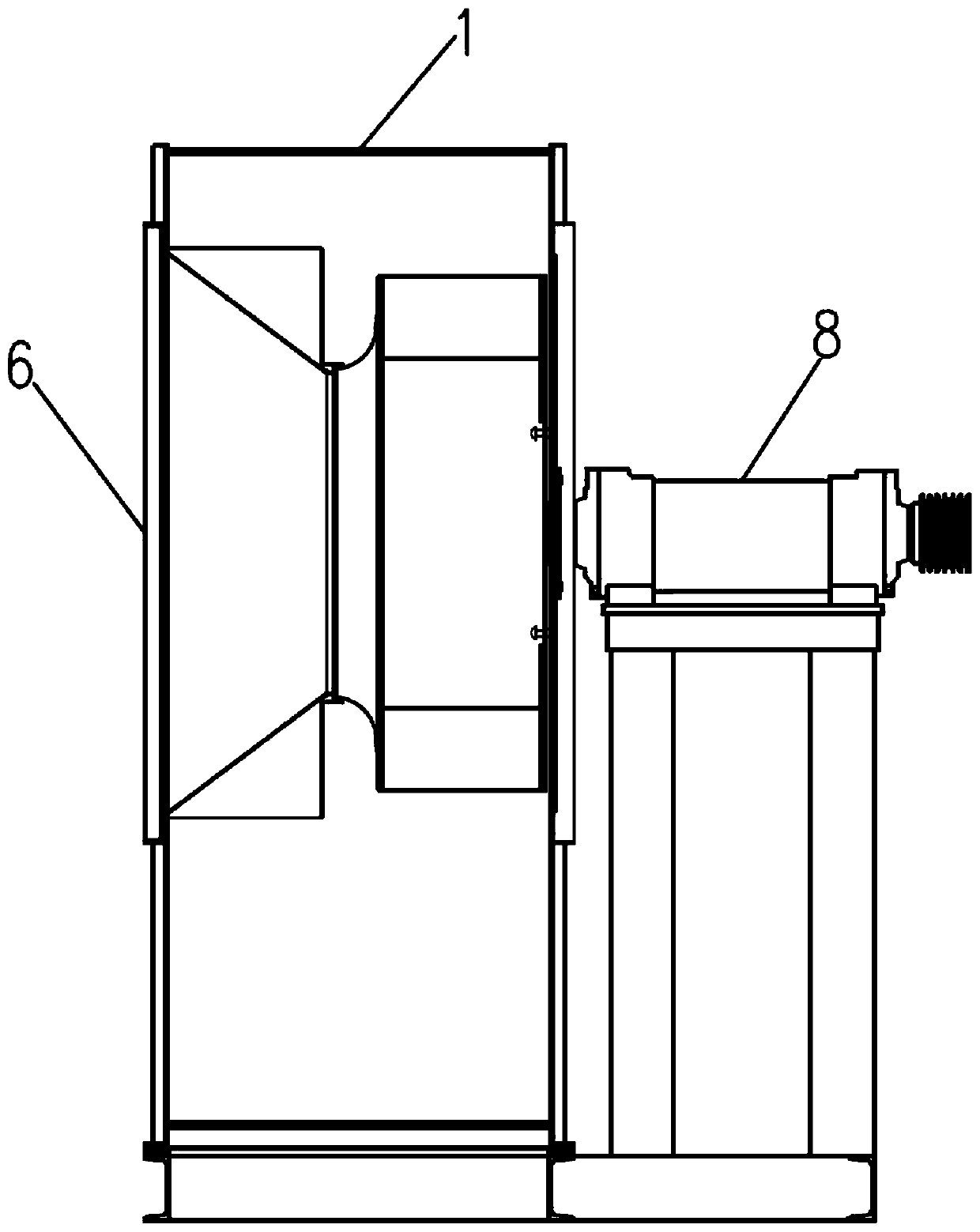
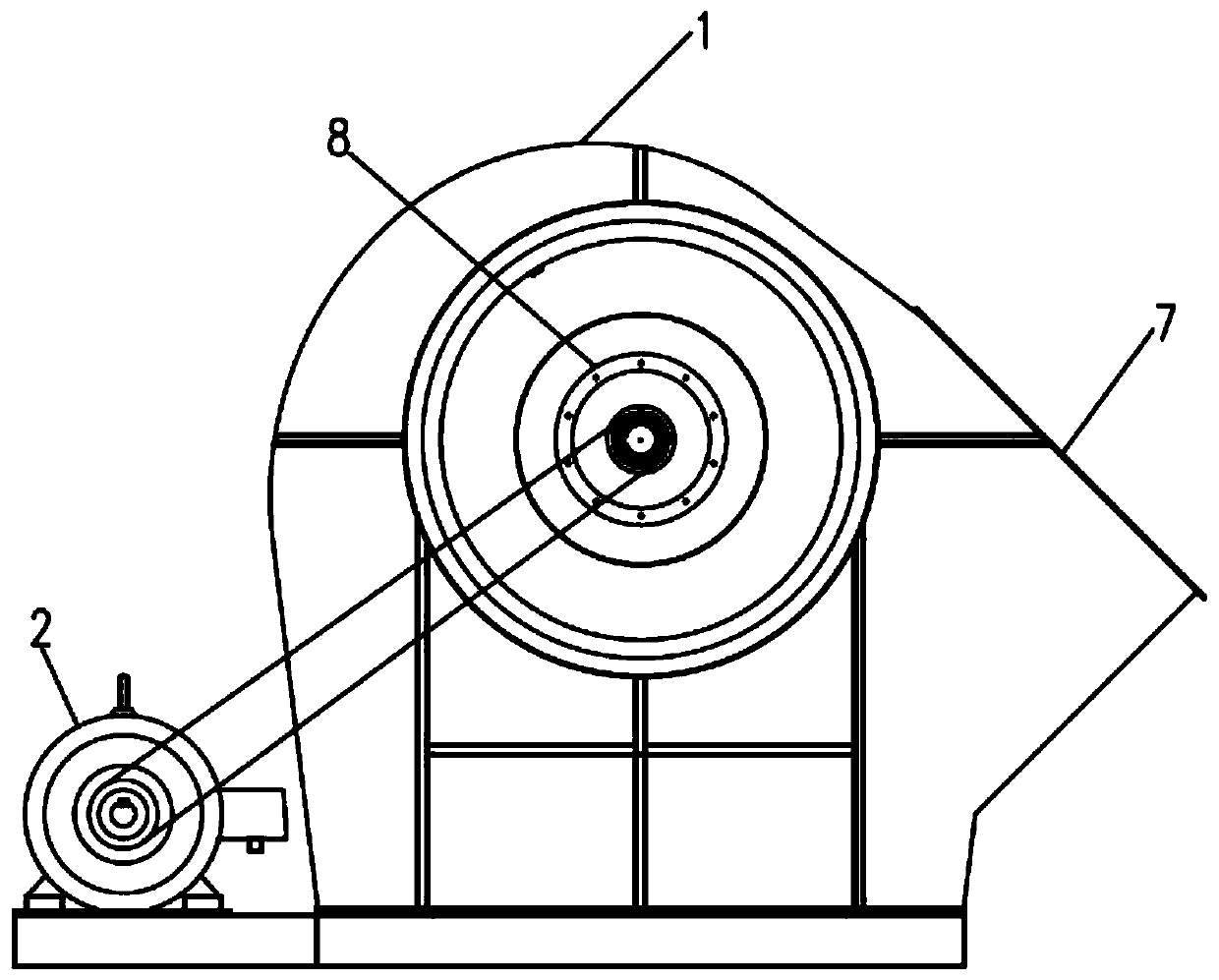
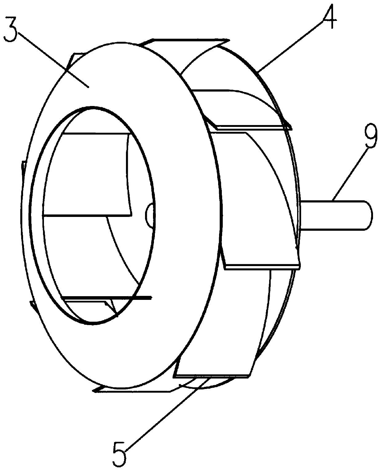
[0024] see figure 1 , figure 2 with image 3 As shown, the device is installed in the volute 1 of the centrifugal fan to form a centrifugal fan: including the drive motor 2, the volute 1 and the air inlet 6 arranged on the left side of the volute 1 and along the tangential direction of the circular shell of the volute 1 The air outlet passage 7 provided is provided with a rotary air centrifugal force generator in the volute 1, and the drive motor 2 drives the rotary air centrifugal force generator to rotate, so that the air in the volute 1 generates centrifugal force, and the air on the side of the air inlet 6 Inhale the air outlet channel 7, the rotary air centrifugal force generating device includes the left side wall plate 3 of the spiral channel, the right side wall plate 4 of the spiral channel and a group of spiral channel partition plates 5, the left side wall plate 3 of the spiral channel is an annular plate, and the annular plate The inner circular hole of the spir...
Embodiment 2
[0027] see figure 1 , figure 2 with Figure 4 As shown, the device is installed in the volute 1 of the centrifugal fan to form a centrifugal fan: including the drive motor 2, the volute 1 and the air inlet 6 arranged on the left side of the volute 1 and along the tangential direction of the circular shell of the volute 1 The air outlet passage 7 provided is provided with a rotary air centrifugal force generator in the volute 1, and the drive motor 2 drives the rotary air centrifugal force generator to rotate, so that the air in the volute 1 generates centrifugal force, and the air on the side of the air inlet 6 Inhalation air outlet channel 7 is characterized in that: the rotary air centrifugal force generating device includes the left side wall plate 3 of the spiral channel and a group of spiral channel partition plates 5, the left side wall plate 3 of the spiral channel is an annular plate, and the inner circular hole of the annular plate Corresponding to the air inlet 6 ...
Embodiment 3
[0031] see figure 1 , figure 2 with Figure 5 As shown, the device is installed in the volute 1 of the centrifugal fan to form a centrifugal fan: including the drive motor 2, the volute 1 and the air inlet 6 arranged on the left side of the volute 1 and along the tangential direction of the circular shell of the volute 1 The air outlet passage 7 provided is provided with a rotary air centrifugal force generator in the volute 1, and the drive motor 2 drives the rotary air centrifugal force generator to rotate, so that the air in the volute 1 generates centrifugal force, and the air on the side of the air inlet 6 Inhale the air outlet channel 7, the rotary air centrifugal force generating device includes the right side wall plate 4 of the spiral channel and a group of spiral channel partition plates 5, the right side wall plate 4 of the spiral channel is a circular plate, and a group of spiral channel partition plates 5 are The arc-shaped plate, the spiral channel partition p...
PUM
 Abstract
Description
Claims
Application Information