Hydraulically powered mine axial flow ventilation fan

An axial flow fan and mine technology, applied in liquid fuel engines, mine/tunnel ventilation, axial flow pumps, etc., can solve the problems of poor bearing force, inconvenient maintenance and poor motor working environment, etc. The effect of stepless speed regulation is easy to achieve, the stress condition is improved, and the maintenance workload is reduced.

Pending Publication Date: 2019-05-03
PINGAN ELECTRICAL
View PDF0 Cites 1 Cited by
  • Summary
  • Abstract
  • Description
  • Claims
  • Application Information

AI Technical Summary

Problems solved by technology

[0007] The purpose of the present invention is to provide a compact structure, large torque, light weight, noise Low cost, long life, easy maintenance hydraulically driven mine axial flow fan

Method used


Image

  • Hydraulically powered mine axial flow ventilation fan
  • Hydraulically powered mine axial flow ventilation fan
  • Hydraulically powered mine axial flow ventilation fan

Examples


Embodiment 1

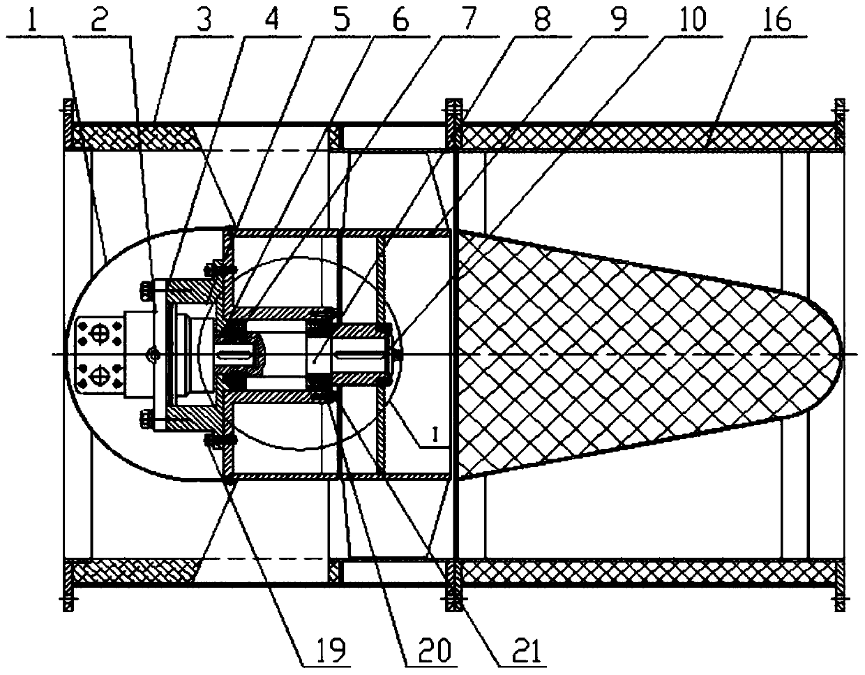
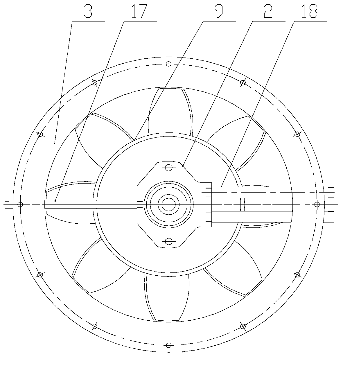
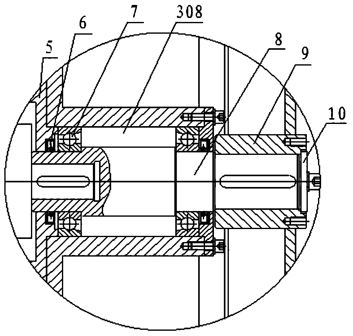
[0036] see Figure 1 to Figure 7 , the hydraulically driven mine axial flow fan of the present embodiment includes an outer shell 3 and a first-stage impeller 9, and the air intake end of the fan is provided with a shroud 1; it also includes an inner cylinder 305, a hydraulic motor 2, and a motor support Seat 5, adapter shaft 8. from figure 1 It can be seen that the shroud 1 is arranged outside the hydraulic motor 2, and the shroud is either a thin-walled hemispherical shape or a semi-closed cone shape. The shroud 1 of this embodiment is a thin-walled hemispherical shape, and the shroud 1 The open end of the inner cylinder body 305 is fixed on the left end face; the air outlet end of the fan in this embodiment is also provided with a shroud, which is a thin-walled semi-closed cone. The inner cylinder 305 is fixedly connected to the inside of the outer shell 3 through the web ribs 306, the right end of the motor support base 5 is fixed to the air inlet end of the left end of ...

Embodiment 2

[0043] see Figure 8 , this embodiment is composed of two such as embodiment 1 figure 1 The vertical sectional view of the hydraulically driven mine axial flow fan composed of the combined fan with counter-rotating structure is shown. Two or more mine hydraulically driven axial flow fans of the present invention with the same specifications are combined into a combined fan with a counter-rotating structure and a multi-stage structure. like Figure 8 As shown, when two axial flow fans form a combined fan with counter-rotating structure, the impellers of the two fans are installed adjacent to each other, and the impellers of the two fans have different numbers of blades, different blade angles, and the impellers rotate in opposite directions. Figure 8 Among them, 9 represents the primary impeller, 11 represents the secondary impeller, 12 represents the first flat key, 14 represents the second flat key, and 15 represents the air outlet diffuser. Figure 8 In all the other lab...

Embodiment 3

[0045] see Figure 9 , this embodiment is a structural schematic diagram of a large axial flow fan driven by hydraulic pressure of the present invention. In this embodiment, the axial flow fan is a counter-rotating mine main fan, and the lower end of the shell has a foot structure, and other support structures can also be used; the hydraulic motor also adopts an axial plunger hydraulic motor, but this is only One of the modes of the hydraulic motor may also be in other structural forms in practical applications.

[0046] from Figure 9 It can be seen in the figure that the inner cylinder of the rear-stage axial flow fan on the right adopts a conical cylinder, and its outer shell is used as a diffuser cylinder or as a part of the diffuser cylinder, and the connecting oil pipe of the hydraulic motor is at the bottom. direction.

[0047] see Figure 10 , is a schematic diagram of the supporting structure of the liquid-driven fan and the hydraulic station of the present invent...


PUM


Abstract

The invention discloses a hydraulically powered mine axial flow ventilation fan. The hydraulically powered mine axial flow ventilation fan comprises an outer shell and an impeller, and further comprises an inner cylinder body, a hydraulic motor, a motor supporting seat and an adapter shaft. A flow guiding cover is arranged at the air inlet end of the fan. The inner cylinder body is fixedly connected to the inner part of the outer shell by a web direction rib plate, one end of the motor supporting seat is fixed to the end part of the air inlet end of the inner cylinder body through a bolt assembly, and the hydraulic motor is fixed to the other end part of the motor supporting seat through a bolt assembly. The shaft extending end of the hydraulic motor extends into an inner hole of the motorsupporting seat and then is connected with the adapter shaft through a flat key or a spline. The adapter shaft is fixed into a bearing box, at the geometric center of the outer shell, of the inner cylinder body through more than two bearings, and the other end of the adapter shaft is connected with an impeller shaft hole through a flat key or a spline. The hydraulic motor is connected with an oilreturn pipe and an oil inlet pipe, and the oil return pipe and the oil inlet pipe are connected to a hydraulic station through a hydraulic control valve after penetrating through the outer shell. Thehydraulically powered mine axial flow ventilation fan has a compact structure, large torque, light weight, low noise, a long service life and convenient maintenance.

Description

technical field [0001] The invention belongs to the technical field of axial flow fans, and in particular relates to a hydraulically driven axial flow fan for mining. Background technique [0002] In ventilation equipment, axial flow fans are generally driven by electric motors. The general structure of the axial flow fan is that the motor is arranged axially in the casing, and the impeller is fixed on the shaft extension of the motor to form a cantilever support. Due to the heavy weight of the impeller, in the actual operation process, there are both radial load and axial load, resulting in poor stress condition of the bearing at the shaft extension end of the motor. In addition, the lubricating conditions of the bearings are not ideal, and the motor bearings burn out and wear prematurely, which often causes the phenomenon of burning the motor. [0003] Considering factors such as motor installation, operation, maintenance, etc., the structural strength of the motor mount...

Claims


Application Information

Patent Timeline
IPC IPC(8): F04D19/00F04D25/04F04D25/08F04D29/32F04D29/054F04D29/056E21F1/00
Inventor 谢星明刘刚秦邦江王海桥张果辉王秀清
Owner PINGAN ELECTRICAL
Why Eureka
Try Eureka