Oil-immersed permanent magnet motor

A permanent magnet motor and oil-immersed technology, applied in the direction of electric components, electrical components, electromechanical devices, etc., can solve the problems of low efficiency, poor replacement and maintenance, and large volume and weight of asynchronous motors, and achieve magnetic steel protection and rotor protection. Integrity and solid reliability, ensuring compact size and good cooling effect

Inactive Publication Date: 2019-05-03
WUHAN MARINE ELECTRIC PROPULSION RES INST CHINA SHIPBUILDING IND CORP NO 712 INST
View PDF9 Cites 6 Cited by
  • Summary
  • Abstract
  • Description
  • Claims
  • Application Information

AI Technical Summary

Problems solved by technology

The oil supply mode of the centralized hydraulic oil pump will make the pipeline complex, occupy a large space, have low redundancy, and poor replacement and maintenance.
[0003] At present, the connection method with many independent oil sources uses the drive motor to connect the hydraulic pump, and the motor is isolated from the hydraulic oil tank. Although the design and requirements of the motor are simplified, it leads to large volume and heavy weight; although a small number of oil-immersed motors have appeared in recent years. Direct drive Hydraulic pump, but the motor is still driven by an ordinary asynchronous motor, and the characteristics of the asynchronous motor itself determine that its efficiency is not high, especially when immersed in hydraulic oil, the viscous loss caused by the small air gap of the asynchronous motor under high-speed rotation is large, resulting in The efficiency is extremely low, generally below 75%, and the volume and weight are too large

Method used


Image

  • Oil-immersed permanent magnet motor
  • Oil-immersed permanent magnet motor
  • Oil-immersed permanent magnet motor

Examples


Embodiment Construction

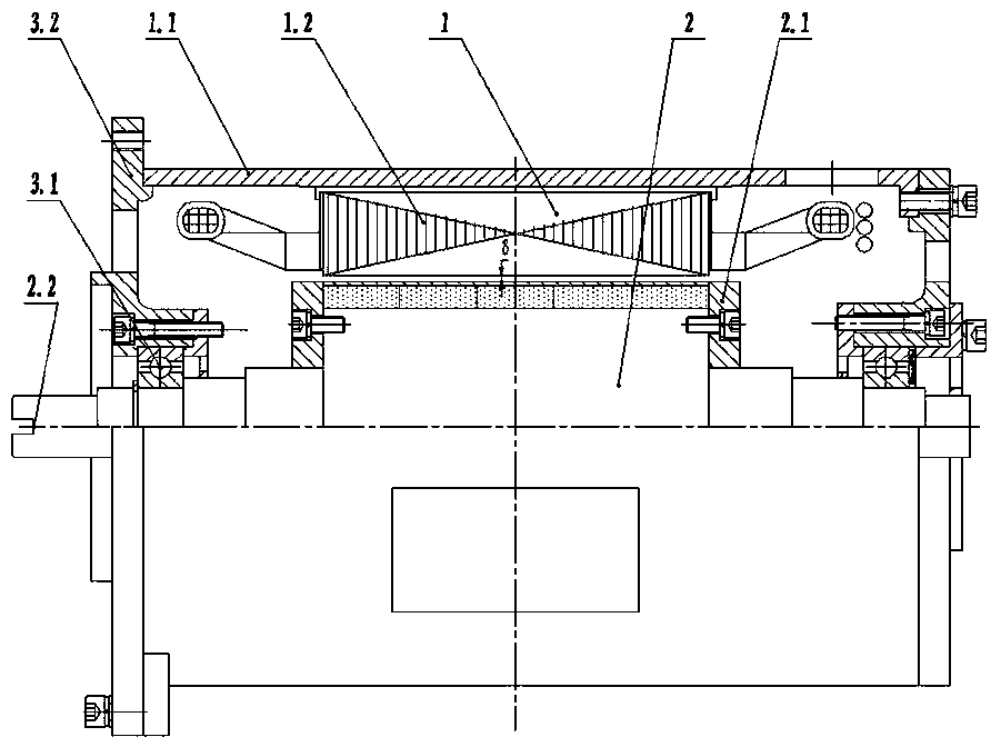
[0030] The present invention will be described in further detail below in conjunction with the accompanying drawings.

[0031] refer to Figure 1 to Figure 5 As shown, the present invention discloses an oil-immersed permanent magnet motor, including a stator 1 and a rotor 2. The size of the air gap between the stator 1 and the rotor 2 not only affects the performance of the motor, but also affects the high-speed rotation of the motor in hydraulic oil. The viscous loss of the motor has a particularly large influence, and the selection of the size of the air gap needs to be calculated and analyzed through fluid dynamics simulation calculations at different temperatures and different speeds to ensure the efficiency and performance of the motor. In the present invention, the recommended air gap δ is 1.5 to 3.5 times larger than that of common asynchronous motors, and the motor rotor 2 with a larger outer diameter and a higher rotational speed takes a larger value. By optimizing t...


PUM


Abstract

The invention discloses an oil-immersed permanent magnet motor, and the motor comprises a stator and a rotor. The stator comprises an engine base and a stator core with a winding. The rotor comprisesa rotating shaft and a rotor end pressing plate. An even number of open slots are formed in the outer surface of the rotating shaft, and T-shaped magnetic steel pressing blocks with taper is fixedly arranged in the open slots. A first magnetic steel strip and a second magnetic steel strip are fixedly arranged in a magnetic steel mounting cavity at an interval. The first magnetic steel strip is composed of a plurality of first magnetic steels with N poles on the outer circumferences and S poles on the inner circumferences, and the second magnetic steel strip is composed of a plurality of secondmagnetic steels with S poles on the outer circumferences and N poles on the inner circumferences. The outer circumferences of the first magnetic steel strip and the second magnetic steel strip are thermally sleeved by sheaths at intervals. According to the invention, the stator and the rotor are uniformly heated, and the cooling effect is good. Meanwhile, the influence on the eccentric magnetic steel is reduced when the sheath is thermally sleeved, and the reliability and the safety are improved. The motor is completely immersed in hydraulic oil, and an eccentric air gap is adopted to improvethe magnetic density waveform scheme, so that the torque ripple and the vibration noise of the motor are small, and the product competitiveness is improved.

Description

technical field [0001] The invention belongs to the technical field of motor-driven hydraulics, and in particular relates to an oil-immersed permanent magnet motor, which is especially suitable for high-speed radial surface-mounted eccentric air-gap inner-rotor permanent magnet motors. Background technique [0002] Hydraulic transmission is one of the main transmission methods of ships. Traditional hydraulic transmission mostly adopts the layout of hydraulic pump station + pipeline. The development trend of all-electric ships in the future requires the use of light and flexible cables instead of bulky pipelines, and the hydraulic actuators distributed in various parts of the ship will use more independent oil source + cable layout. The oil supply mode of the centralized hydraulic oil pump will make the pipeline complex, occupy a large space, have low redundancy, and poor replacement and maintenance. [0003] At present, the connection method with many independent oil source...

Claims


Application Information

Patent Timeline
Patent Type & Authority Applications(China)
IPC IPC(8): H02K1/28H02K1/27H02K7/14
Inventor 周贵厚谭波张国兵祝后权
Owner WUHAN MARINE ELECTRIC PROPULSION RES INST CHINA SHIPBUILDING IND CORP NO 712 INST
Why Eureka
Try Eureka