Water cooling heat dissipation power module used for rail transit

A power module, water-cooling heat dissipation technology, applied in the direction of AC power input conversion to DC power output, output power conversion device, cooling/ventilation/heating transformation, etc., can solve the problem of weight and volume increase of permanent magnet synchronous traction drive system, system Increased design difficulty, increased heat dissipation power of the power module, etc., to achieve the effect of saving design and development investment, convenient maintenance and compact structure

Pending Publication Date: 2019-05-03
重庆中车四方所科技有限公司
View PDF0 Cites 3 Cited by
  • Summary
  • Abstract
  • Description
  • Claims
  • Application Information

AI Technical Summary

Problems solved by technology

[0002] The permanent magnet synchronous traction drive system has gradually been applied in rail transit vehicles, but the control of the permanent magnet synchronous motor can only be controlled by the axis, that is, one inverter unit can only control one permanent magnet synchronous motor, which also leads to the permanent magnet synchronous motor. Compared with the asynchronous motor traction drive system, the magnetic synchronous traction drive system requires more inverter units, resulting in an increase in the weight and volume of the permanent magnet synchronous traction drive system
[0003] Traditional forced air-cooled power modules or natural cooling power modules can only use one side of the radiator for power device layout, which is bulky and heavy. If the permanent magnet synchronous traction system uses forced air-cooled or natural cooling power modules, it will inevitably lead to power As the number of modules increases, the size and weight of the system will also increase significantly
At the same time, due to the increase of inverter units, the overall heat dissipation power of the power module will also increase, resulting in an increase in the difficulty of system design

Method used


Image

  • Water cooling heat dissipation power module used for rail transit
  • Water cooling heat dissipation power module used for rail transit
  • Water cooling heat dissipation power module used for rail transit

Examples


Embodiment Construction

[0023] The implementation of the present invention will be illustrated by specific specific examples below, and those skilled in the art can easily understand other advantages and effects of the present invention from the contents disclosed in this specification.

[0024] Below in conjunction with accompanying drawing and embodiment the present invention will be further described:

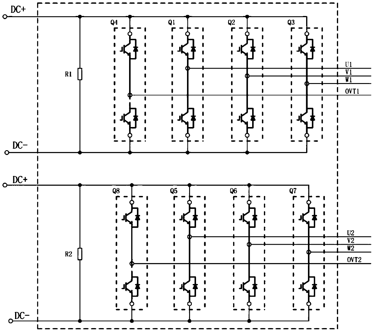
[0025] refer to figure 1 As shown, the rail transit water-cooled heat dissipation power module of this embodiment integrates two traction inverter units, and each inverter unit is composed of Q1-Q4 and Q5-Q8 respectively, wherein Q1 and Q5 are the two inverter units respectively. U-phase bridge arms, Q2 and Q6 are V-phase bridge arms, Q3 and Q7 are W-phase bridge arms, and Q4 and Q8 are chopping bridge arms. At the same time, each inverter unit integrates fixed loads R1 and R2, which simplifies the system layout.

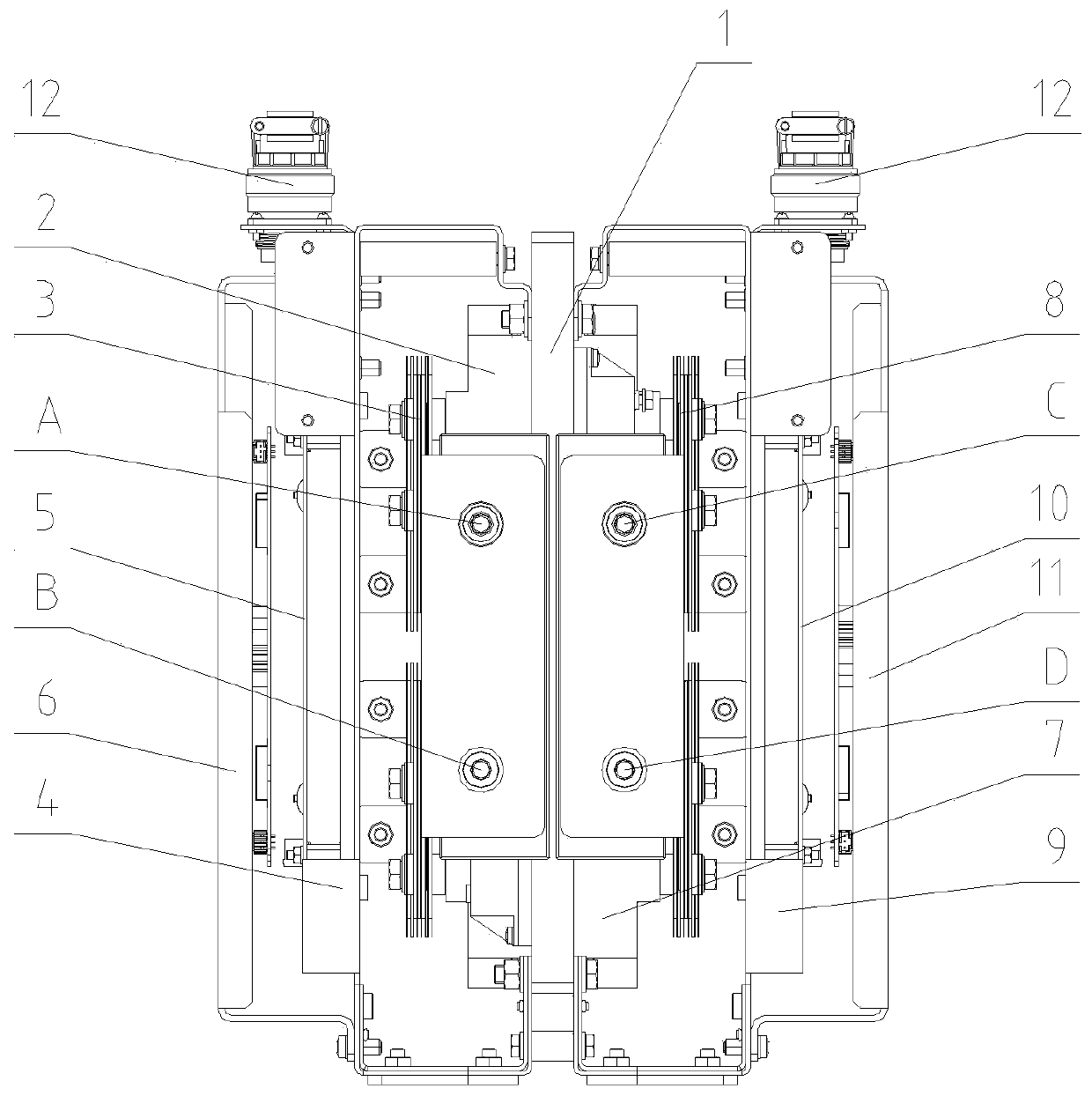
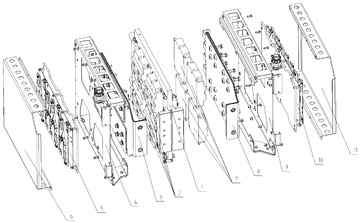
[0026] see figure 2 , image 3 , Figure 4 , the power module also includes a ...


PUM


Abstract

The invention discloses a water cooling heat dissipation power module used for rail transit. The module includes a water cooling plate and two inversion units which are arranged on both sides of the water cooling plate; the inversion units include IGBT power units, composite busbars, mounting plates, IGBT driving boards, and optical fiber connectors; after the bottom surfaces of the IGBT power units are coated with thermally conductive silicone grease, the IGBT power units are installed on the surface of the water cooling plate, the IGBT power units are connected with the composite busbars, the mounting plates are directly fixed on the surface of the water cooling plate and plays a supporting role, and the IGBT driving boards are mounted on the mounting plates; and the optical fiber connectors are mounted on the mounting plates, and the optical fiber connectors adopt multi-core photoelectric integrated connectors. The water cooling heat dissipation power module used for the rail transit has the characteristics of light weight and integration, can achieve integration of two or more inversion units on one power module, and has high heat dissipation efficiency.

Description

technical field [0001] The invention belongs to the technical field of heat dissipation for rail transit systems, and in particular relates to a water-cooled heat dissipation module. Background technique [0002] The permanent magnet synchronous traction drive system has gradually been applied in rail transit vehicles, but the control of the permanent magnet synchronous motor can only be controlled by the axis, that is, one inverter unit can only control one permanent magnet synchronous motor, which also leads to the permanent magnet synchronous motor. Compared with the asynchronous motor traction drive system, the magnetic synchronous traction drive system requires more inverter units, resulting in an increase in the weight and volume of the permanent magnet synchronous traction drive system. [0003] Traditional forced air-cooled power modules or natural cooling power modules can only use one side of the radiator for power device layout, which is bulky and heavy. If the pe...

Claims


Application Information

Patent Timeline
Patent Type & Authority Applications(China)
IPC IPC(8): H02M7/00H02M7/48H05K7/20
Inventor 薛浩飞吴新安李国银刘炬张洋吴晶王旭阳杨吉徐先伟谭运
Owner 重庆中车四方所科技有限公司
Why Eureka
Try Eureka