Goggle inner lifting-type face mask
A technology for goggles and face shields, which is applied in goggles, goggles, ophthalmic surgery, etc. It can solve the problems of unstable center of gravity, easily damaged goggles, and poor vision of eversion-type masks, and achieves simple structure and avoids welding spatter , Ease of replacement and installation
- Summary
- Abstract
- Description
- Claims
- Application Information
AI Technical Summary
Problems solved by technology
Method used
Image
Examples
Embodiment 1
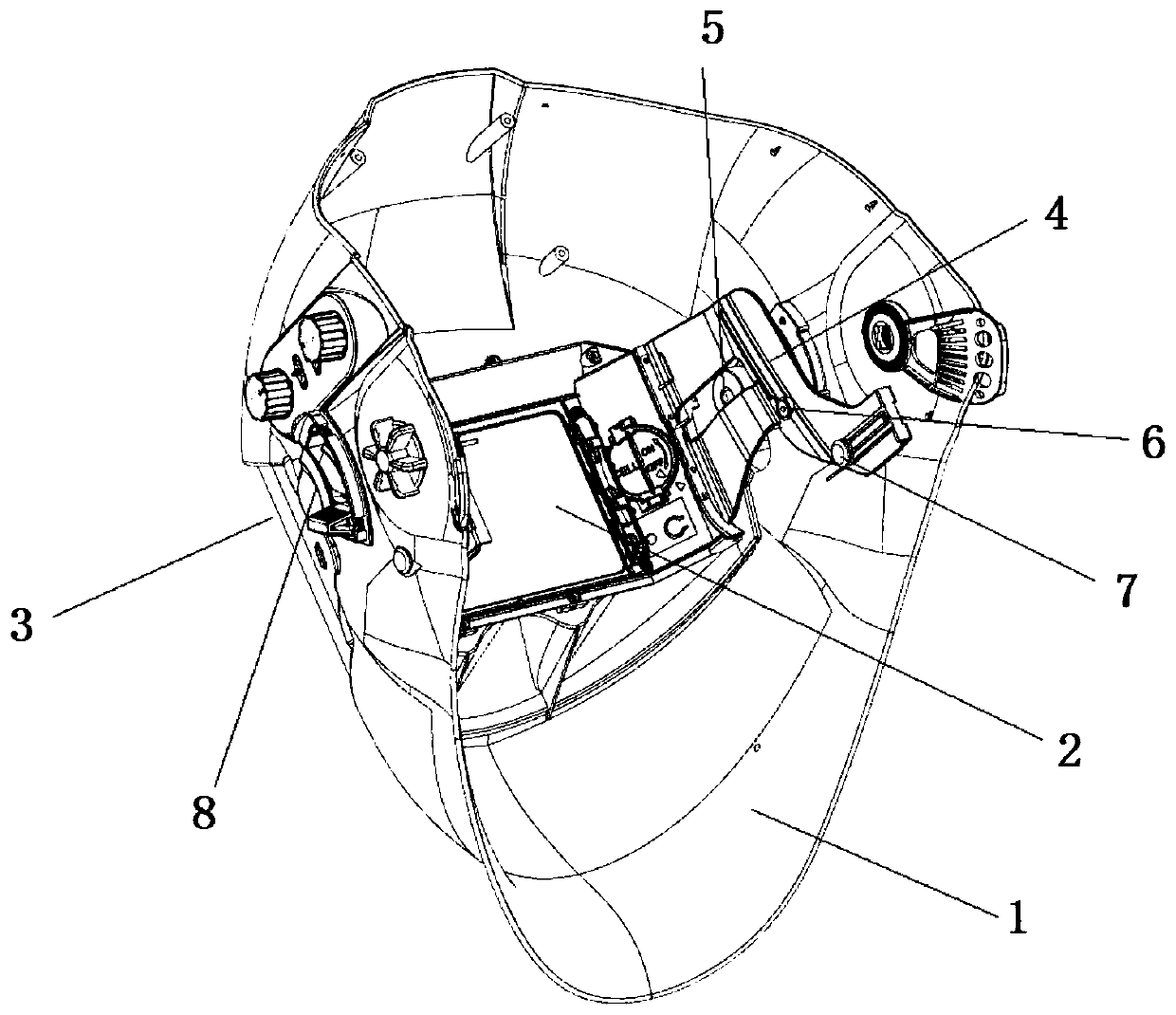
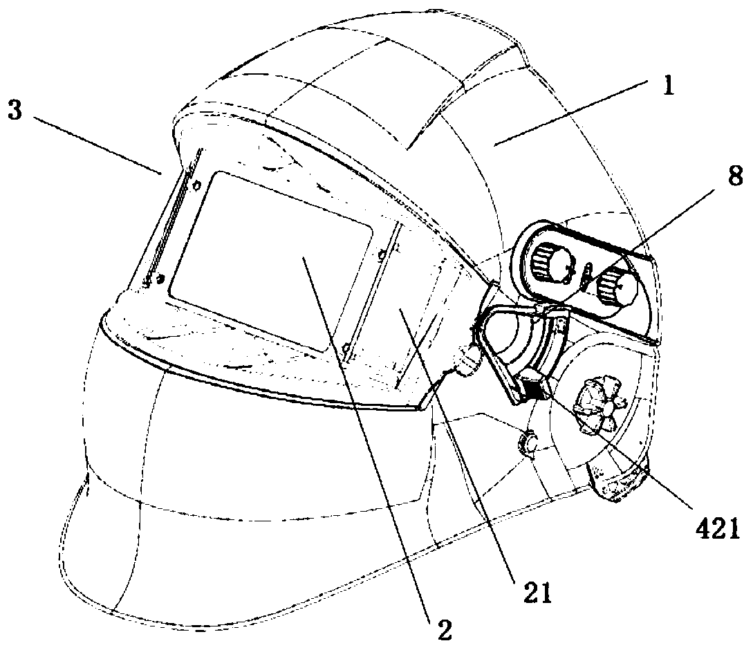
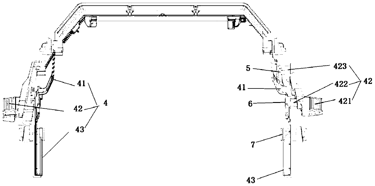
[0050] Such as Figure 1-3 As shown, the present embodiment is a kind of flip-up face shield inside the goggles, including a mask body 1, goggles 2, front protective mirror 3, linkage mechanism 4, first connecting shaft 5, second connecting shaft 6, third connecting shaft 7, limit plate 8; front protective mirror 3 is fixed on the front side of mask body 1, and goggles 2 are fixed on the link mechanism 3, and link mechanism 3 can adjust the rotation of goggles 2 and is connected to mask body 1 both sides, connects The rod mechanism 4 can adjust the upward rotation of the goggles 2. The goggles 2 are inside the mask body 1, the rear side of the front protective mirror 3, and are closer to the eyes; the first connecting shaft 5 and the third connecting shaft 7 are in a fixed state , the second connecting shaft 6 is in a state where it can move in an arc shape, and the positions of the first connecting shaft 5 , the second connecting shaft 6 and the third connecting shaft 7 are s...
Embodiment 2
[0065] Such as Figure 14 As shown, the difference between the second embodiment and the first embodiment is that the second hollow cylinder 422 is arranged on a connecting piece 44, and the connecting piece 44 and the rocker link 42 are in a split structure, and the second hollow cylinder 422 is not directly arranged on the rocker link 42;
[0066] The rocker link 42 is connected to the link frame 41 through a connecting piece 44, and the connecting piece 44 is fixedly connected to the rocker link 42, which can be screwed, clamped, bonded, etc. , connected between the handle 421 and the sleeve 423, to ensure that the middle part of the link frame 41 is fixedly connected with the end of the rocker link 42, and the position corresponding to the handle 421 on the connector 44 is provided with the second connecting shaft 6. The second hollow cylinder 422 that is fixedly connected. The connecting rod frame 41 is provided with a round hole 412 corresponding to the second connectin...
Embodiment 3
[0068] The difference between the third embodiment and the first embodiment is that the positioning of the rocker link 42 is different. In the embodiment, the positioning is realized by the buckle 4211 and the two slots 82; in this embodiment, the positioning pin is inserted into the slot 82 way of positioning.
[0069] The tail of the limiting plate 8 is provided with at least two draw-in slots 82. In this embodiment, there are two draw-in slots 82. The interior of the handle 421 is hollow. When the handle 421 moves to a draw-in slot 82, the hollow of the handle is in the draw-in slot. 82 alignment, at this time, the positioning pin is inserted into the slot 82 and extended to the hollow inside the handle 421 to realize positioning; when the station needs to be replaced, the positioning pin is pulled out, and the handle 421 is moved to another slot 82, Insert the positioning pin into the slot 82 and extend to the hollow inside the handle 421 to achieve positioning at other po...
PUM
 Abstract
Description
Claims
Application Information
 - R&D
- Intellectual Property
- Life Sciences
- Materials
- Tech Scout
- Unparalleled Data Quality
- Higher Quality Content
- 60% Fewer Hallucinations
Browse by: Latest US Patents, China's latest patents, Technical Efficacy Thesaurus, Application Domain, Technology Topic, Popular Technical Reports.
© 2025 PatSnap. All rights reserved.Legal|Privacy policy|Modern Slavery Act Transparency Statement|Sitemap|About US| Contact US: help@patsnap.com


