Novel tire glue spraying machine and using method thereof

A glue-spraying machine and glue-spraying technology, which is applied to devices and coatings that apply liquid to the surface, can solve the problems of uneven flow of the glue, large differences in the thickness of the sprayed layer, and weakening of the fluidity of the glue. The effect of uniform distribution of glue quantity, uniform coating thickness and precise flow control

Inactive Publication Date: 2019-05-07
浙江宽途智能科技有限公司
View PDF6 Cites 3 Cited by
  • Summary
  • Abstract
  • Description
  • Claims
  • Application Information

AI Technical Summary

Problems solved by technology

[0003] Existing tire glue spraying machine, there are many problems in use: 1. Existing tire glue spraying machine, because there are two glue outlet holes on the glue spraying head, the liquid glue is sprayed to the shoulder of the inner wall of the tire at a fixed point Parts, use the rotation of the tire to drive the flow of the rubber material, let the liquid rubber material flow and close from both sides to the middle, and form a closed coating layer, but when the rubber material flows from the two sides to the middle, the temperature will continue to drop, which will reduce the rubber material and the inner wall of the tire. Adhesive strength, the fluidity of the rubber material becomes weaker when the temperature drops, resulting in uneven flow of the rubber material, resulting in uneven thickness of the coating layer and easy generation of air bubbles; Fixed value, not adjustable or changeable
Therefore, tires of different specifications and different models use the same glue spraying speed, resulting in a large difference in the thickness of the inner wall sprayed layer between different specifications and different models of tires, thereby affecting the spraying effect; 3. The existing tire glue spraying machine adopts The air pressure pump provides the transmission pressure of the fluid material, but the air pressure is affected by the air pump itself, and the output air pressure cannot be stabilized, which makes it difficult to accurately control the glue spraying speed and the glue spraying flow rate

Method used


Image

  • Novel tire glue spraying machine and using method thereof
  • Novel tire glue spraying machine and using method thereof
  • Novel tire glue spraying machine and using method thereof

Examples


Embodiment Construction

[0035] The technical solution of this patent will be further described in detail below in conjunction with specific embodiments.

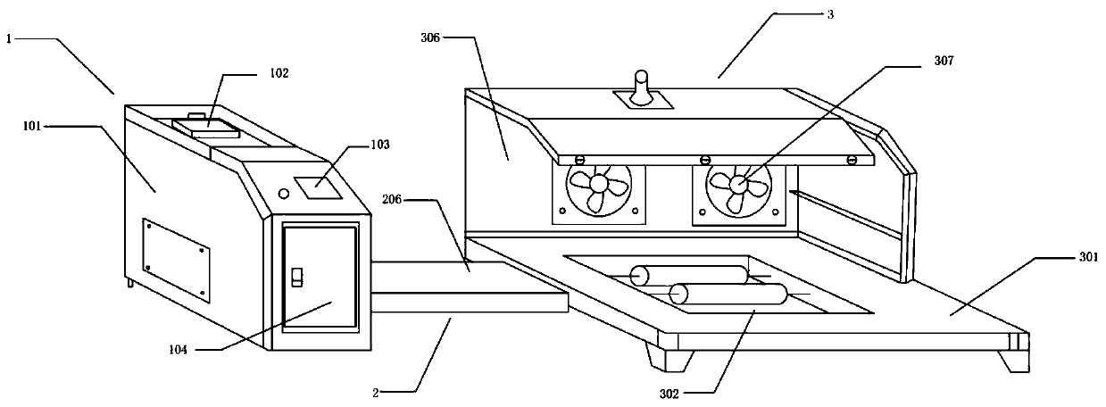
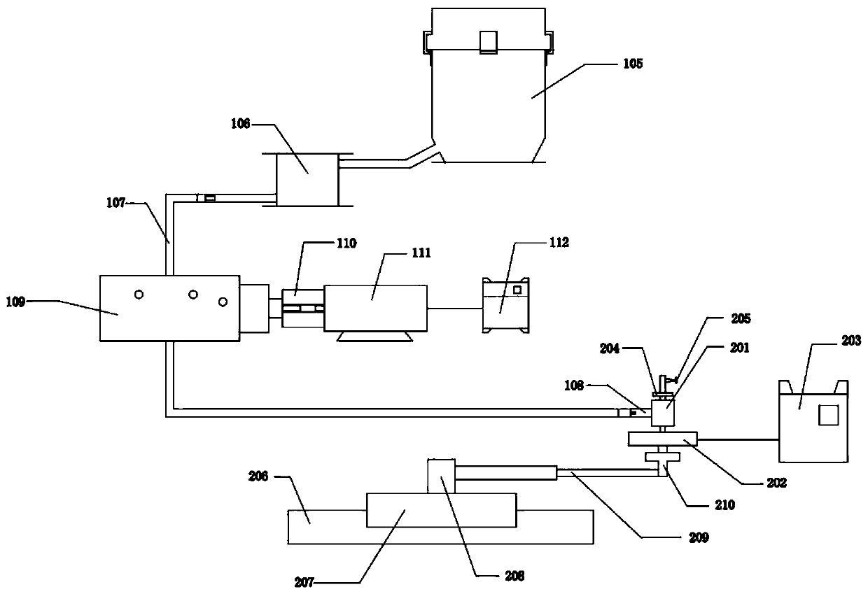
[0036] see Figure 1-8As shown, a new type of tire glue spraying machine includes a chassis mechanism 1, a glue spray mechanism 2, and a worktable mechanism 3; the chassis mechanism 1 includes a box body 101, and an upper slot 102 is opened above the box body 101, The top of the upper slot 102 is equipped with an upper slot cover, the side of the casing 101 is equipped with a touch screen 103, and the inside of the touch screen 103 is equipped with a control CPU. The main slot 104 is arranged directly below the touch screen 103, and the main slot 104 The main tank cover is installed, and the staff can check and repair the internal parts of the box body 101 through the main slot hole. The inside of the cabinet 101 is equipped with a melting glue bucket 105. To realize feeding, the bottom of the melting glue barrel 105 is connected to the glue stora...


PUM


Abstract

The invention discloses a novel tire glue spraying machine and a using method thereof, belongs to the field of tire deep processing equipment, and particularly relates to the novel tire glue sprayingmachine. The novel tire glue spraying machine comprises a machine box mechanism, a glue spraying machine body and a workbench mechanism. The novel tire glue spraying machine and the using method havethe beneficial effects that the safety during working is improved, output air pressure is stabilized, the flow accuracy is further controlled, the glue spraying amount is controlled to be uniformly distributed, the generation of bubbles is reduced, and the thickness of the coating layer is uniform; and tires with different specifications and different models can be met, and the problem that the thickness difference of the inner wall spraying layers among the tires of different specifications and different models is large is fundamentally solved.

Description

technical field [0001] The invention relates to the technical field of glue spraying, in particular to a novel tire glue spraying machine and a method for using the same. Background technique [0002] With the development of science and technology, automobiles, motorcycles and other means of transportation have gradually become people's means of transportation. If conventional tires are used, there will be dangers of tire punctures and blowouts during driving. At this time, it is necessary to go to a repair shop for repairs. fetal. In order to improve the safety performance of vehicles during driving, the production of safety tires has emerged as the times require. At present, the production process of anti-puncture and puncture-resistant safety tires generally uses a rubber material that is in a soft solid state and has a high viscosity. It is realized on the inner cavity wall of the tire carcass. [0003] Existing tire glue spraying machine, there are many problems in us...

Claims


Application Information

Patent Timeline
Patent Type & Authority Applications(China)
IPC IPC(8): B05C5/00B05C11/10B05C13/02B05C9/12
Inventor 杜汇丰丁其诚王卫东陶皓
Owner 浙江宽途智能科技有限公司
Why Eureka
Try Eureka