Secondary phase error compensation method and device for digital holographic microscopy
A technology of digital holographic microscopy and secondary phase error, which is applied to measurement devices, optical devices, instruments, etc., can solve the problem of inability to eliminate secondary phase errors, etc. Secondary phase error, the effect of low system cost
- Summary
- Abstract
- Description
- Claims
- Application Information
AI Technical Summary
Problems solved by technology
Method used
Image
Examples
Embodiment 1
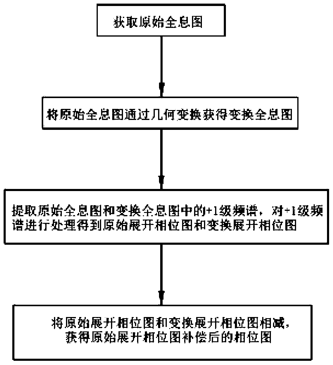
[0059] This embodiment includes the following steps:
[0060] Step S101, using a digital holographic microscope system to collect a hologram of the object to be tested as an original hologram;
[0061] Specifically, this embodiment uses a digital holographic microscope system as a system structure, and uses a CCD camera in the digital holographic microscope system to collect a hologram of the object to be measured as an original hologram.
[0062] Step S102, performing a 180° transformation operation on the original hologram to obtain a digital reference hologram as a transformed hologram;
[0063] Specifically, the present invention only needs to collect one hologram, and then perform a 180° rotation transformation operation on the hologram to obtain another digital reference hologram as a transformation hologram.
[0064] Step S103, using the Fourier transform method in the digital holographic microscope to perform phase recovery processing on the original hologram to obtai...
Embodiment 2
[0072] Embodiment 2 is the same as Embodiment 1 in terms of steps and flow, except that in step S102, the original hologram is flipped upside down to obtain a digital reference hologram as a transformed hologram.
[0073] In order to test the effectiveness of the quadratic phase compensation method based on the up-down flip transformation, in this embodiment, a simulated microsphere is selected as the object to be measured to obtain a corresponding quadratic phase error compensation result. image 3 is the phase distribution of the simulated microsphere, Figure 4 is the original hologram of the object to be tested. After the original hologram is flipped up and down, the up and down flipped transformed holograms are obtained as follows: Figure 10 shown. For the hologram, the Fourier transform method is used to extract the +1-level spectrum respectively, and the obtained unfolded phase distribution is as follows: Figure 5 , Figure 11 As shown, according to the method prop...
Embodiment 3
[0075] Embodiment 3 is the same as Embodiment 1 in terms of steps and flow, except that in step S102, the original hologram is flipped left and right to obtain a digital reference hologram as a transformed hologram.
[0076] In order to test the effectiveness of the quadratic phase compensation method based on the left-right flip transformation, in this embodiment, a simulated microsphere is selected as the object to be measured to obtain a corresponding quadratic phase error compensation result. image 3 is the phase distribution of the simulated microsphere, Figure 4 is the original hologram of the object to be tested. After the original hologram is flipped left and right, the left and right flipped transformed holograms are obtained as follows: Figure 14 shown. For the hologram, the Fourier transform method is used to extract the +1-level spectrum respectively, and the obtained unfolded phase distribution is as follows: Figure 5 , Figure 15 As shown, according to the...
PUM
 Abstract
Description
Claims
Application Information
 - R&D
- Intellectual Property
- Life Sciences
- Materials
- Tech Scout
- Unparalleled Data Quality
- Higher Quality Content
- 60% Fewer Hallucinations
Browse by: Latest US Patents, China's latest patents, Technical Efficacy Thesaurus, Application Domain, Technology Topic, Popular Technical Reports.
© 2025 PatSnap. All rights reserved.Legal|Privacy policy|Modern Slavery Act Transparency Statement|Sitemap|About US| Contact US: help@patsnap.com


