Automatic cooker for kitchen

A cooking machine and automatic technology, which is applied in the direction of kitchen utensils, cooking utensil lids, plug-ins, etc., can solve the problems of increasing kitchen staff, requiring manual participation, and unfavorable work for chefs

Active Publication Date: 2019-05-10
张维加
View PDF18 Cites 19 Cited by
  • Summary
  • Abstract
  • Description
  • Claims
  • Application Information

AI Technical Summary

Problems solved by technology

[0002] With the rapid development of the economy, people's pace of life is getting faster and faster. In terms of catering, more and more office workers choose to eat in fast food restaurants, restaurants, etc., and there are more and more consumers who eat fast. Correspondingly, the labor intensity of restaurant kitchen staff will increase, and increasing the number of kitchen staff will increase the labor cost of the restaurant, and too many kitchen staff are not conducive to the chef's work in a narrow kitchen. Therefore, cooking machine ...

Method used


Image

  • Automatic cooker for kitchen
  • Automatic cooker for kitchen
  • Automatic cooker for kitchen

Examples


Embodiment 1

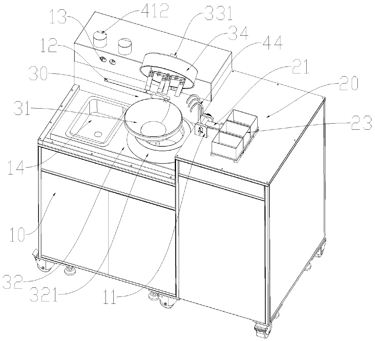
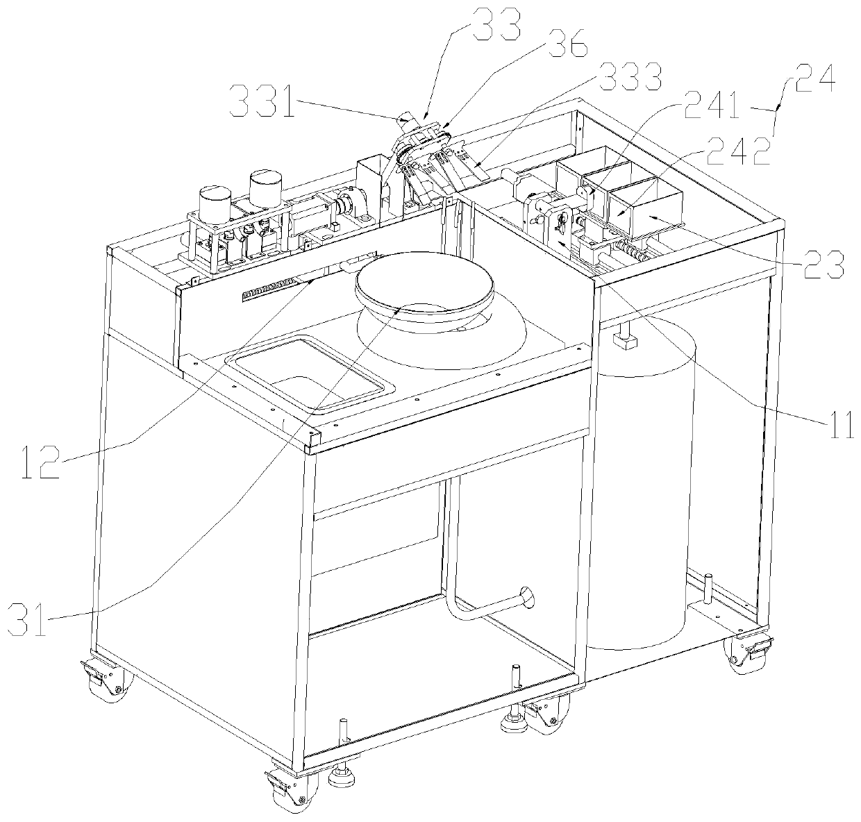
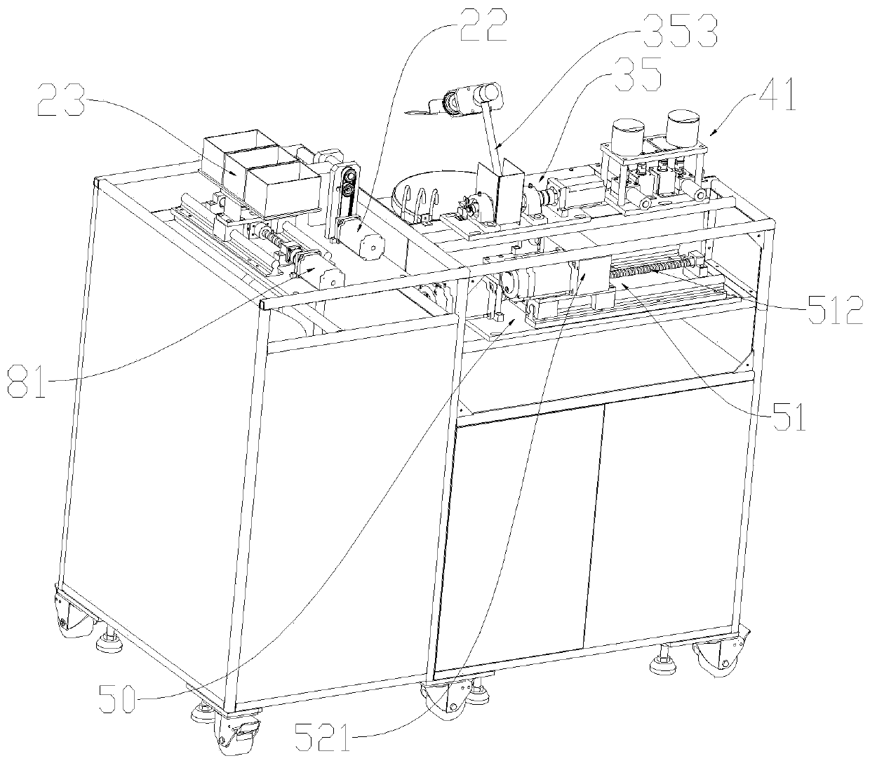
[0048] attached Figure 1-15 A kitchen automatic cooking machine is shown, see Figure 1 to Figure 4 , comprising a machine platform 10, the machine platform 10 is provided with a dish delivery unit 20, a dish processing unit 30, a seasoning delivery unit 40 and a cooked dish delivery unit 50, wherein:

[0049] see figure 1 with Figure 5, the dish delivery unit 20 comprises a rotating rod 21, a motor A22 and several vegetable boxes 23, the vegetable box 23 is arranged on the machine platform 10, the rotating rod 21 is arranged between the vegetable box 23 and the dish processing unit 30, and one end of the rotating rod 21 is arranged There is an adsorption device 24 for absorbing the vegetable box 23, the other end of the rotating rod 23 is provided with a rotating shaft 25, the machine table 10 is provided with a mounting plate 11, and the rotating shaft 25 is rotatably located on the mounting plate 11 to realize the rotation of the rotating shaft 25. The purpose of being...

Embodiment 2

[0069] This embodiment is the same as embodiment one except the following content:

[0070] see Figure 16 to Figure 18 , Stir-fry mechanism 33 comprises motor B331, rotating bar 37 and stirring bar 38, the output shaft of motor B331 connects the middle part of rotating bar 37, and rotating bar 37 is threadedly connected with stirring bar 38, and stirring bar 38 is located at the top of wok 31, When stir-frying dishes, the stir-frying mechanism 33 is lowered to the inside of the frying pan 31, driven by the motor B331, the rotating bar 37 drives the stirrer 38 to rotate, and the rotating stirrer 38 can realize the stirring of the stirrer 31. The dishes in the interior are stirred and stir-fried, and the stirring rod 38 is threadedly connected with the rotating bar 37, which is convenient for changing and overhauling the stirring rod 38. The output shaft of the motor B331 is connected to the middle part of the rotating bar 37, which is conducive to fully stirring the dishes.


PUM


Abstract

The invention relates to an automatic cooker for a kitchen, comprising a cabinet, wherein a disk feeding unit, a dish processing unit, a seasoning feeding unit and a cooked food delivering unit are arranged on the cabinet; the feeding unit comprises a rotary rod, a motor A, a dish box and an adsorbing device, and the adsorbing device is arranged on the rotary rod; the dish processing unit comprises a heating device, a stir pan and a stir-frying mechanism used for stirring and frying the dish in the stir pan, the stir pan is located above the heating device, and the stir-frying mechanism is located above the stir pan; the seasoning feeding unit comprises a solid seasoning feeding unit and a liquid seasoning feeding unit; the cooked food delivering unit comprises a stir pan delivering mechanism and a stir pan dumping mechanism, so as to realize the functions of automatic dish feeding, automatic stirring and frying, automatic and quantitative feeding of seasonings and automatic dumping ofdishes, further realize the aim of automatic cooking dishes, and further reducing the work intensity of personnel of the kitchen and effectively saving human cost.

Description

technical field [0001] The invention relates to the technical field of cooking equipment, in particular to an automatic kitchen cooking machine. Background technique [0002] With the rapid development of the economy, people's pace of life is getting faster and faster. In terms of catering, more and more office workers choose to eat in fast food restaurants, restaurants, etc., and there are more and more consumers who eat fast. Correspondingly, the labor intensity of restaurant kitchen staff will increase, and increasing the number of kitchen staff will increase the labor cost of the restaurant, and too many kitchen staff are not conducive to the chef's work in a narrow kitchen. Therefore, cooking The machine came into being. [0003] However, most of the current cooking machines are still in a semi-automatic or extensive stage, and cannot be fully automatic. They have basically realized that the stir-frying process in the cooking process is completed by machines instead of...

Claims


Application Information

Patent Timeline
IPC IPC(8): A47J27/00A47J36/00A47J36/06A47J36/16A47J36/34
Inventor 张维加
Owner 张维加
Why Eureka
Try Eureka