
Branched Vascular Stent

A technology of vascular stents and branch tubes, which is applied in the direction of stents, blood vessels, and devices of human tubular structures, can solve the problems of insufficient deployment of short branches 113, complicated operation, and insufficient deployment of short branches, so as to avoid insufficient deployment, The effect of increasing the expansion space

Active Publication Date: 2021-07-20
LIFETECH SCI (SHENZHEN) CO LTD
View PDF0 Cites 0 Cited by
  • Summary
  • Abstract
  • Description
  • Claims
  • Application Information

AI Technical Summary

Problems solved by technology

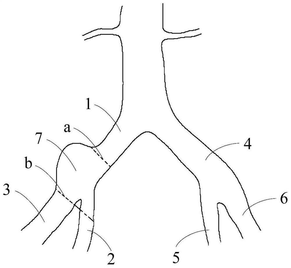
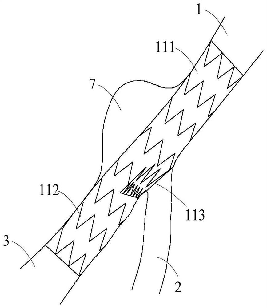
However, when the branched stent is implanted at the aneurysm 7 of the right internal iliac artery 2, there is not enough space on the side of the right internal iliac artery for the short branch 113 to expand, so when the branched stent is implanted into the aneurysm 7 of the right internal iliac artery. When there are 7 aneurysms, the short branch 113 is easily compressed by the wall of the right common iliac artery 1 and the branched vascular stent, resulting in insufficient expansion or even complete closure of the short branch 113
When the short branch 113 is insufficiently deployed or completely closed and the channel of the right internal iliac artery 2 needs to be reconstructed, a right internal iliac artery stent needs to be implanted. However, the operation of implanting the right internal iliac artery stent through the short branch 113 is very complicated, and may even leading to the failure of the entire implant surgery
[0006] In this regard, it is necessary to propose a new branched vascular stent in view of the technical problem that the short branch is squeezed by the wall of the blood vessel after the existing branched vascular stent is implanted into the blood vessel, resulting in insufficient expansion or even complete closure.

Method used


Image

  • Branched Vascular Stent
  • Branched Vascular Stent
  • Branched Vascular Stent

Examples


specific Embodiment 1

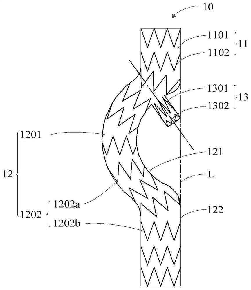
[0041] Specific embodiment one: as image 3 As shown, the first branched vascular stent 10 with overall shape memory characteristics provided by the first embodiment includes a hollow first stent main tube 11, a hollow first long branch tube 12 and a hollow first short branch tube 13. The proximal end of a long branch pipe 12 is connected to the distal end of the first stent main pipe 11, and the first long branch pipe 12 is provided with a section of first elbow 121. Towards the configuration that returns to the predetermined shape after restraint), the first extension line L of the edge of the right side (the side opposite to the bending direction of the first elbow 121) of the first stent main pipe 11 and the first long branch pipe 12 Enclosed at the first elbow 121 to form a first bending area (such as image 3 In the blank area between the first extension line L and the first elbow 121), one end of the first short branch pipe 13 is arranged in the first bending area and ...

specific Embodiment 2

[0048] Specific embodiment two: as Figure 8 As shown, the present embodiment provides a second branched vascular stent 10', and the second curved tube on the second long branch tube 12' in the second branched vascular stent 10' is set as a zigzag-shaped curved tube 1201' , the proximal end of the curved pipe 1201' in a zigzag structure communicates with the distal end of the second stent main pipe 11', and the distal end of the curved pipe 1201' in a zigzag structure communicates with the second straight pipe 1202' on the second long branch pipe 12'. The proximal end is connected, and the second extension line L' of the right edge of the second stent main pipe 11' and the second long branch pipe 12' are enclosed at the second bend to form a second bending area, and the second short branch pipe 13 One end of 'is arranged in the second bending area and communicates with the inside of the second elbow. Please refer to Figure 9 , the curved pipe 1201' with a zigzag structure i...

specific Embodiment 3

[0049] Specific embodiment three: as Figure 11 and Figure 12 As shown, the present embodiment provides a third branched vascular stent 20, the distal end of the third curved tube 2201 on the third branched vascular stent 20 is at the proximal end of the third straight tube 2202 of the third long branched tube 22 The communicating portion is provided with a protruding structure 2203 opposite to the bending direction of the third curved pipe 2201 , that is, the protruding structure 2203 is disposed on the side of the third straight pipe 2202 away from the third curved pipe 2201 and protrudes outward. In the third embodiment, the protruding structure 2203 crosses the third extension line 24 of the right edge of the third stent main tube 21 and faces to the right side of the third branched vascular stent 20 (opposite to the bending direction of the third curved tube 2201 one side of the third stent main pipe 21, and the raised structure 2203 of the third extension line 24 beyon...


PUM


Abstract

The invention relates to the technical field of interventional medical devices, in particular to a branched blood vessel stent. The invention provides a branched vascular stent, which has shape memory characteristics, and includes a main tube, a long branch tube and a short branch tube that are all hollow inside, the proximal end of the long branch tube is connected to the distal end of the main tube of the stent and Connected, the long branch pipe is provided with a bend pipe, in the expanded configuration, the bend pipe and the extension line of the edge of the bracket main pipe away from the bend pipe form a bending area, and one end of the short branch pipe is set at the bend area and communicate with the inside of the elbow. The present invention forms a bending area by arranging a section of bent tube on the long branch tube, and arranges the short branch tube in the bending area, so as to avoid the phenomenon that the short branch tube cannot be expanded due to being squeezed by blood vessels.

Description

technical field [0001] The invention relates to the technical field of interventional medical devices, in particular to a branched blood vessel stent. Background technique [0002] This section provides background information related to the present disclosure only and is not necessarily prior art. [0003] Hypertension (hypertension) refers to a chronic disease characterized by an increase in systemic arterial blood pressure (systolic and / or diastolic) (systolic blood pressure ≥ 140 mm Hg, diastolic blood pressure ≥ 90 mm Hg). The incidence of blood pressure has risen sharply, and the incidence of other diseases related to arteries (such as aneurysm) has also shown a significant upward trend. With the development of medicine, straight tubular stent grafts are generally used to treat aneurysms. In the process of treating aneurysms, the compressed straight tubular stent grafts are first loaded into the delivery system, and then The stent graft is delivered to the position of...

Claims


Application Information

Patent Timeline
Patent Type & Authority Patents(China)
IPC IPC(8): A61F2/07A61F2/89
Inventor 黄新鑫肖本好
Owner LIFETECH SCI (SHENZHEN) CO LTD
Learn More