Small square blank vertical drawing continuous casting machine and pressing process device

A process device and a small billet technology, applied in the field of continuous casting production, can solve the problems of limited reduction capacity, inability to achieve efficient reduction, and low coverage of steel grades, and achieve the effect of improving the density of the center

Inactive Publication Date: 2019-05-10
NORTHEASTERN UNIV
View PDF11 Cites 2 Cited by
  • Summary
  • Abstract
  • Description
  • Claims
  • Application Information

AI Technical Summary

Problems solved by technology

[0003] Patent application CN102000789A "a continuous casting machine and billet light reduction device", patent application CN106345977A "secondary cooling method and device for high-speed billet or billet continuous casting machine" and patent application CN206527325U "billet continuous The above-mentioned studies on "Casting Machine" all proposed the casting method with the wide surface as the width direction. Although the pressing device is also used, the coverage of the steel type is low, and the actual on-site production requirements of multiple steel types and cross-sections cannot be realized, and the pressing capacity is limited. Cannot achieve efficient compression

Method used


Image

  • Small square blank vertical drawing continuous casting machine and pressing process device
  • Small square blank vertical drawing continuous casting machine and pressing process device
  • Small square blank vertical drawing continuous casting machine and pressing process device

Examples


Embodiment 1

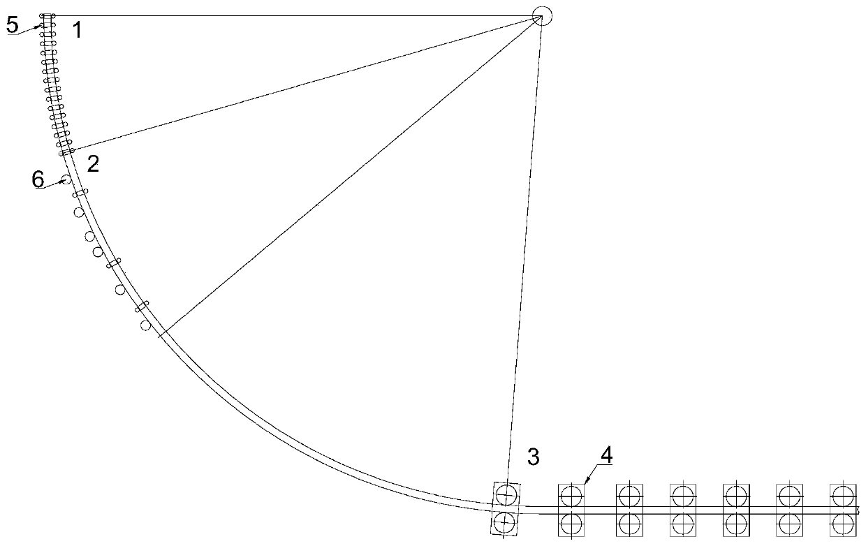
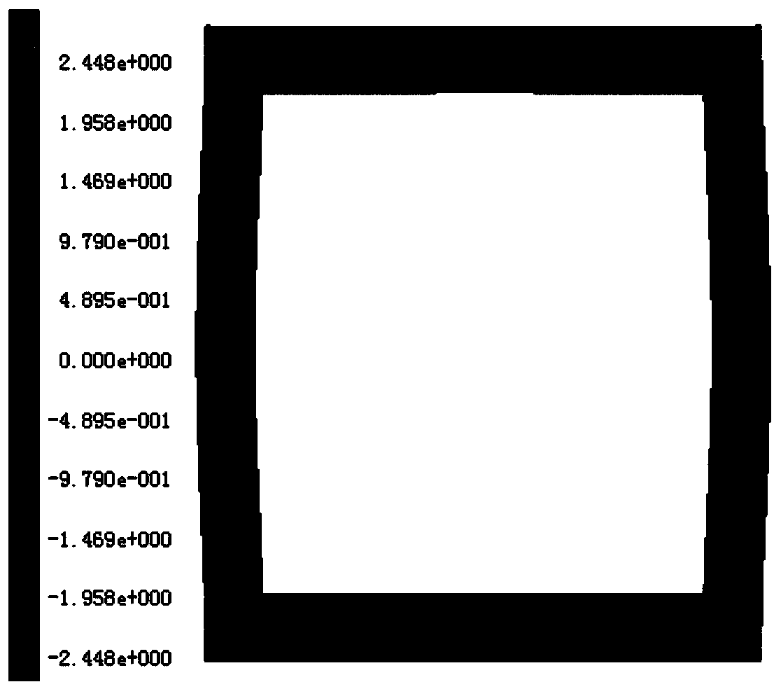
[0023] Such as figure 1 As shown, this example provides a kind of billet vertical casting machine and pressing process device, described billet vertical casting machine, such as figure 2 As shown at 2.3m away from the meniscus, since the billet shell thickness here is 15mm and the belly volume is 2.448mm, it is necessary to continuously implement four-sided clamping rolls on the foot roll section. That is, constraints are carried out in both the width and thickness directions of the slab.

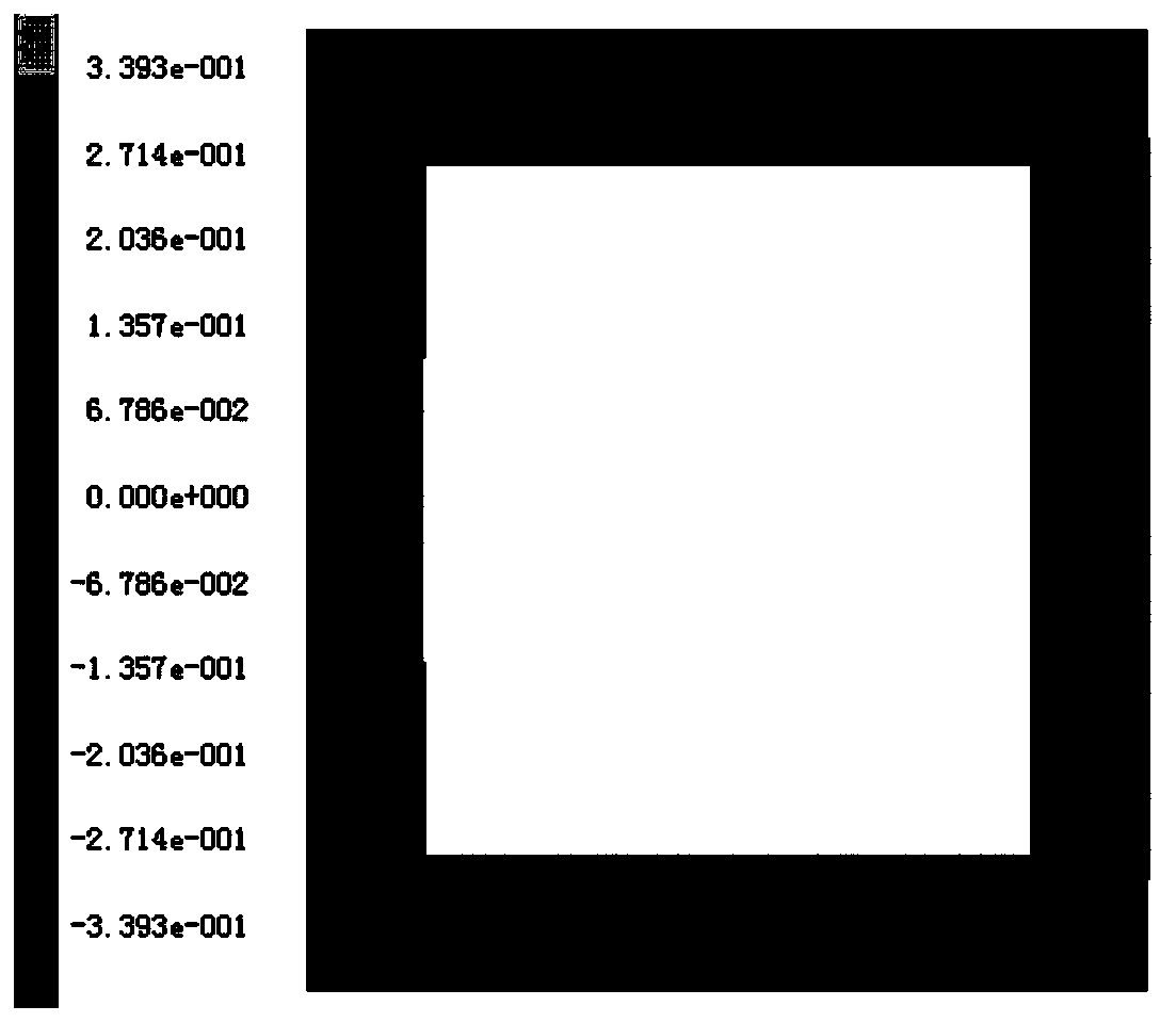
[0024] In the described billet vertical drawing continuous casting machine and the reduction process device, the secondary cooling zone 2 adopts segmented four-sided clamping of the casting roll 5, such as image 3 , 4 As shown at 3.8m and 5.3m from the meniscus, the thickness of the shells at the two places is 20mm and 25mm respectively, and the bulges are 0.339 and 0.0874mm respectively. Therefore, in order to further ensure the billet shape, the control of the bulges is arranged in th...


PUM

PropertyMeasurementUnit
solid fractionaaaaaaaaaa

Abstract

The invention relates to a small square blank vertical drawing continuous casting machine and a pressing process device. The small square blank vertical drawing continuous casting machine and the pressing process device comprises a full four-side clamping foot roll section, a two-cooling zone four-side clamping roll column and a press-down process device, and the full four-side clamping foot rollsection is restrained in the width and the thickness direction of a casting blank; at least three groups of four-side clamping roll columns are arranged in the two-cooling area, and the rest is a lower carrier roller; the pressing process device is arranged in a casting blank solidification tail end region and adopts a single-machine frame form, wherein each machine frame is composed of an upper pressing roller and a lower pressing roller, and a rolling gap formed between the upper pressing roller and the lower pressing roller and the using number of the pressing process devices corresponds tothe specifications of the small square billets, steel type and the on-site actual pulling speed. According to the small square blank vertical drawing continuous casting machine and the pressing process device, the density of the center of the casting blank can be effectively improved, so that the central shrinkage hole of the casting blank is achieved, and the segregation can be effectively controlled. It is guaranteed that the casting blank can effectively control the bulging of the casting blank in a vertical blank drawing mode to ensure the shape of the casting blank, after the follow-up casting blank is subjected to a pressing process, a square enters the steel rolling process to serve as bedding.

Description

technical field [0001] The invention relates to a billet continuous casting machine, belonging to the field of continuous casting production, in particular to a billet vertical casting continuous casting machine and a pressing process device. Background technique [0002] The traditional billet continuous casting machine adopts the way that the wide side is the width direction, and the narrow side is the thickness. The upper and lower nip rolls are lowered to restrict the width direction, and the secondary cooling system is used to spray the surface of the billet to ensure that the billet shell There is no large belly volume. In order to meet the quality requirements of the variety of steel and reduce segregation and porosity inside the slab, electromagnetic stirring of the mold or a combination of double electric stirring at the mold and solidification end is often used. The configuration of electric stirring technology is only suitable for low casting speed production. Wh...

Claims


Application Information

Patent Timeline
Patent Type & Authority Applications(China)
IPC IPC(8): B22D11/12
Inventor 祭程朱苗勇李应焕吴晨辉
Owner NORTHEASTERN UNIV
Why Eureka
Try Eureka