Efficient plate shearing machine

A shearing machine, high-efficiency technology, applied in the direction of shearing device, shearing machine equipment, shearing machine accessories, etc., can solve the problems of low efficiency, achieve high flexibility, wide application range, and improve stability

Inactive Publication Date: 2019-05-10
安徽省通快数控机床制造有限公司
View PDF6 Cites 0 Cited by
  • Summary
  • Abstract
  • Description
  • Claims
  • Application Information

AI Technical Summary

Problems solved by technology

[0003] In view of the shortcomings of the prior art described above, the purpose of the present invention is to provide a high-efficiency shearing machine for solving the problem of low efficiency of the existing shearing machine when cutting short plates

Method used


Image

  • Efficient plate shearing machine
  • Efficient plate shearing machine
  • Efficient plate shearing machine

Examples


Embodiment 1

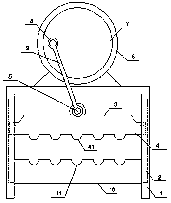
[0021] Such as Figure 1-4 As shown, the present invention discloses a high-efficiency plate shearing machine, comprising a frame 1 and a binder plate 34, the frame 1 is an inverted U shape, and the inner walls of the left and right sides of the frame 1 are respectively provided with chute 2. A tool holder 3 is slidably connected in the chute 2; a blade 4 is fixedly connected to the lower end of the knife holder 3, and a plurality of blades 41 are uniformly arranged on the lower end of the blade 4; the middle of the upper end of the tool holder 3 is fixedly connected There is a rotating shaft one 5; the upper end of the frame 1 is fixedly connected with a turret 6, and the rotating frame 6 is connected with a rotating disk 7; the front plane of the rotating disk 7 is fixedly connected with a rotating shaft 2 8, and the rotating shaft 2 8 is located at the position where the turntable 7 is far away from the center of the circle, the first rotating shaft 5 is rotationally connec...


PUM


Abstract

The invention relates to the technical field of plate shearing machines, in particular to an efficient plate shearing machine. Sliding chutes are arranged in the inner walls of the left side and the right side of the machine frame respectively, a knife rest are slidably connected in the sliding chutes; a blade are fixedly connected to the lower end of the knife rest, a plurality of knife edges areuniformly arranged at the lower end of the blade; a rotating shaft I is fixedly connected to the middle of the upper end of the knife rest; the upper end of the machine frame is fixedly connected with a rotating frame, the rotating frame is rotationally connected with a rotating disc; a rotating shaft II is fixedly connected to the front plane of the rotating disc, the rotating shaft I is rotationally connected with one end of the connecting rod, and the other end of the connecting rod is rotationally connected with the rotating shaft II; feeding plates are fixedly connected to the lower endsof the left inner wall and the right inner wall of the machine frame, a plurality of longitudinal feeding grooves are uniformly arranged in the feeding plate; transverse feeding grooves are arrangedin the feeding plates, the position of the feeding grooves are corresponded to blades position; and a plurality of feeding mechanisms are arranged on the feeding plates, a power mechanism is arrangedon the machine frame. The efficient plate shearing machine has the advantages of being high in cutting efficiency, convenient to use, high in flexibility and capable of improving the cutting stabilityand the like.

Description

technical field [0001] The invention relates to the technical field of shearing machines, in particular to a high-efficiency shearing machine. Background technique [0002] The shearing machine is mainly used for cutting metal plates. The shearing machine is widely used in industrial production due to its superior performance. The existing shearing machines are powered by hydraulic cylinders and are mainly used for shearing large plates. cutting, but it seems overkill to cut the plate into small sections, and the efficiency of the existing shears to cut the plate into small sections is also very low; patent application number: CN201721072903.6 discloses a shearing machine that can be combined with slotting, There is a workbench in front of the lower part of the shearing machine body, a supporting plate is arranged on the working platform, a plurality of rollers are installed on the supporting plate, a lifting rod is arranged above the supporting plate, and the bottom of the ...

Claims


Application Information

Patent Timeline
IPC IPC(8): B23D15/08B23D15/12B23D33/00B23D33/02B23Q11/10
Inventor 王小元
Owner 安徽省通快数控机床制造有限公司
Why Eureka
Try Eureka