Method for machining thin-wall separation type solid retainer

A technology of a solid cage and a processing method, which is applied in the field of thin-walled separation-type solid cage processing, can solve the problems of low machining precision of the rivet holes of the cage, difficulty in ensuring product processing quality, and difficulty in machining the cage, and achieves guaranteed machining. Consistency of accuracy and size, improvement of machining accuracy, reduction of turning stress and deformation

Active Publication Date: 2019-05-10
AVIC HARBIN BEARING
View PDF16 Cites 6 Cited by
  • Summary
  • Abstract
  • Description
  • Claims
  • Application Information

AI Technical Summary

Problems solved by technology

[0016] In order to solve the problems of the existing thin-wall separable bearing solid cages, which are difficult to process, easily deformed, have low precision in the inner and outer diameters of the cage and the processing precision of rivet holes, and are difficult to guarantee the processing quality of the products, the present invention further provides a A kind of thin-wall separated solid cage processing method

Method used


Image

  • Method for machining thin-wall separation type solid retainer
  • Method for machining thin-wall separation type solid retainer
  • Method for machining thin-wall separation type solid retainer

Examples


specific Embodiment approach 1

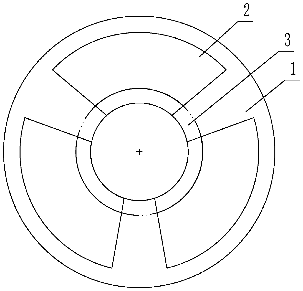
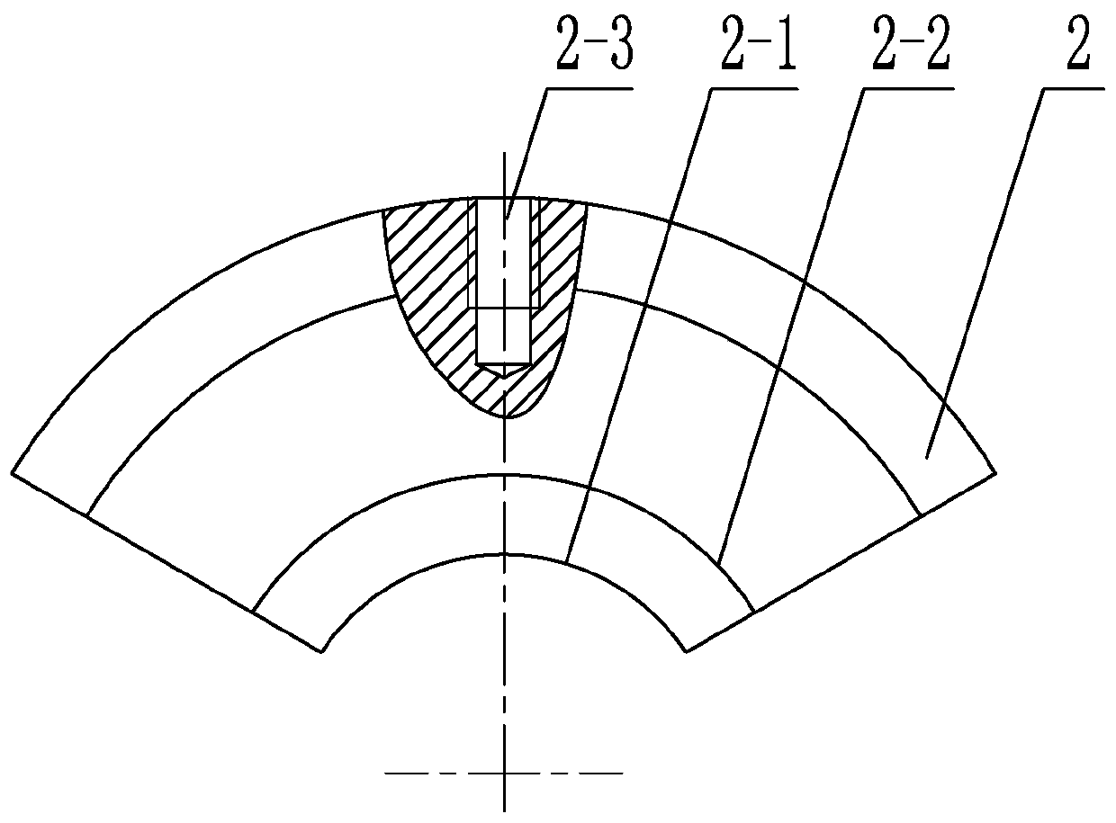
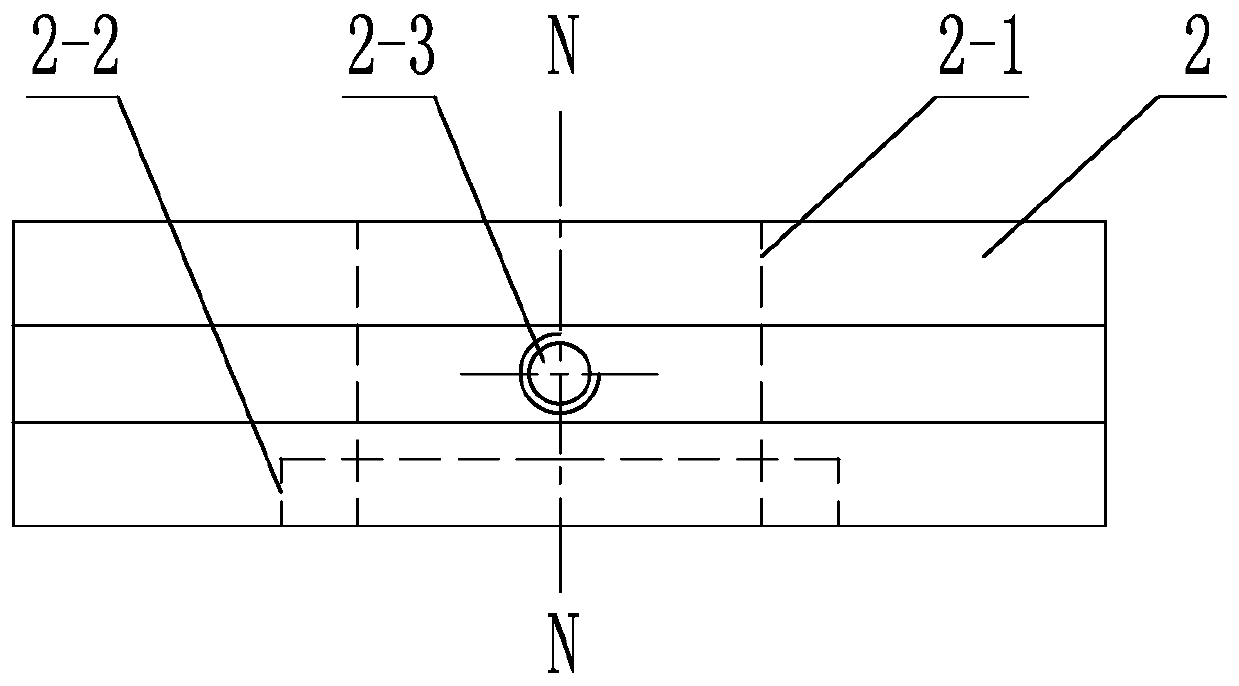
[0065] Specific implementation mode one: combine Figure 1 to Figure 3 Describe this embodiment, a thin-wall separation type solid cage processing method in this embodiment, the thin-wall separation type solid cage processing method is realized by the following steps,

[0066] Step 1. Fine turning the first plane, second plane, rough grinding outer diameter, and fine turning inner diameter in turn:

[0067] Install the molded cage on the lathe, finely process the first plane and the second plane of the cage, install the cage after fine turning two planes on the grinding machine, rough grind the outer diameter of the cage, and then Install the cage after rough grinding the outer diameter on the lathe, and finely process the inner diameter of the cage. The rough grinding outer diameter is 0.2-0.3 mm for the fine grinding outer diameter, and the fine turning inner diameter is 0.3-0.4 mm for the fine turning inner diameter. mm;

[0068] Step two, solid solution strengthening:

...

specific Embodiment approach 2

[0091] In this embodiment, when the outer diameter is finally ground, the dispersion of the outer diameter is controlled at 0~+0.02mm, and the ellipticity of the outer diameter VDcp0.006~0.01mm. The outer diameter is the guide surface of the cage and is also a relatively important part of the cage. , the required processing accuracy is relatively high, so the processing accuracy must be guaranteed during processing. Embodiment 2: The machining tolerance of the rivet holes described in step 6 of this embodiment is reduced to 0-+0.05 mm. In this way, the finished product drawing requires the processing tolerance of the rivet hole to be ±0.05mm. In order to achieve the universal assembly of the rivet hole processing, the processing tolerance of the rivet hole is compressed to +0.05mm, and the carbide drill bit is selected, which has high hardness and is durable. Wear and tear, the diameter and size of the processed rivet holes are stable, so that two and a half cages can be rivet...

specific Embodiment approach 3

[0092] Embodiment 3: The minimum processing size of the rivet hole described in step 6 of this embodiment is Φ0.8 mm. Other compositions and connections are the same as those in Embodiment 1 or Embodiment 2.


PUM

PropertyMeasurementUnit
hardnessaaaaaaaaaa

Abstract

The invention discloses a method for machining a thin-wall separation type solid retainer, and relates to the technical field of design and manufacture of retainers. According to the method, the problems that an existing thin-wall separation type bearing solid retainer is large in machining difficulty, easy to deform, the interior of the retainer, the outer diameter precision and the rivet hole machining precision are low, and the product machining quality is difficult to guarantee are solved; the method for machining the thin-wall separation type solid retainer is realized through the following steps that 1, finely turning is sequentially carried out on a first plane and a second plane, the outer diameter is coarsely ground and finely turning is carried out on the inner diameter; 2, solidsolution strengthening is carried out; 3, turning are both carried out on two planes ; 4, the finely turning is carried out on the outer diameter; 5, the inner diameter is finely ground; 6, a rivet hole is drilled; 7, a bolt is inserted; 8, a pocket is drilled and milled; 9, the outer diameter is finally milled; 10, final turning is carried out on the inner diameter; 11, the bolt is removed, deburring is carried out, and finishing is carried out; and 12, fluorescent permeation flaw detection is carried out. The method is used for improving the interior of the retainer, the outer diameter precision and the rivet hole machining precision of the thin-wall separation type solid retainer.

Description

technical field [0001] The invention relates to the technical field of retainer design and manufacture, in particular to a processing method for a thin-wall separated solid retainer. Background technique [0002] Separable bearing cages are widely used in deep groove ball bearings. The main function of the cage is to keep the rolling elements at an appropriate distance from each other to reduce the frictional moment of the bearing and the heat generated by friction; to make the rolling elements evenly distributed. In the whole bearing, to optimize the load distribution and reduce noise; to guide the rolling elements in the no-load zone to improve rolling conditions and prevent damaging sliding. It can be seen that the cage plays a vital role in the bearing. [0003] Thin-walled structure bearing cages are more common in recent years, and are widely used in the bearing industry due to their advantages of light weight, material saving, and compact structure. Although there ar...

Claims


Application Information

Patent Timeline
Patent Type & Authority Applications(China)
IPC IPC(8): B23P15/00
Inventor 曹阳刘颖志唐双晶薛雪张翔纪春华于寒王心刘新强高强毕立行杜杰张帅陈泽卉王雷范继承周英侽王德军杜存秀朱磊
Owner AVIC HARBIN BEARING
Why Eureka
Try Eureka