Magnetic fluid modular mechanical gripper and working method thereof

A mechanical gripper, magnetic fluid technology, applied in the directions of manipulators, chucks, manufacturing tools, etc., can solve the problem that the rack and pinion mechanism occupies a large space, the worm gear and worm mechanism have low mechanical efficiency, and is not suitable for heavy-load mechanical work, etc. problems, to achieve the effect of easy disassembly and assembly, easy transportation management, and small footprint

Pending Publication Date: 2019-05-10
哈工大机器人(山东)智能装备研究院
View PDF11 Cites 0 Cited by
  • Summary
  • Abstract
  • Description
  • Claims
  • Application Information

AI Technical Summary

Problems solved by technology

For large-load manipulators, the most important thing is to reduce energy consumption as much as possible. The mechanical efficiency of the worm gear mechanism is very low, and it is not suitable for large-load mechanical work; the rack-and-pinion mechanism occupies a large space and is inconvenient to operate; the wedge The pneumatic chuck can greatly reduce the torque required for pitching, and the control is relatively simple, but the application space is small and the direction change is limited

Method used


Image

  • Magnetic fluid modular mechanical gripper and working method thereof
  • Magnetic fluid modular mechanical gripper and working method thereof
  • Magnetic fluid modular mechanical gripper and working method thereof

Examples


Embodiment 1

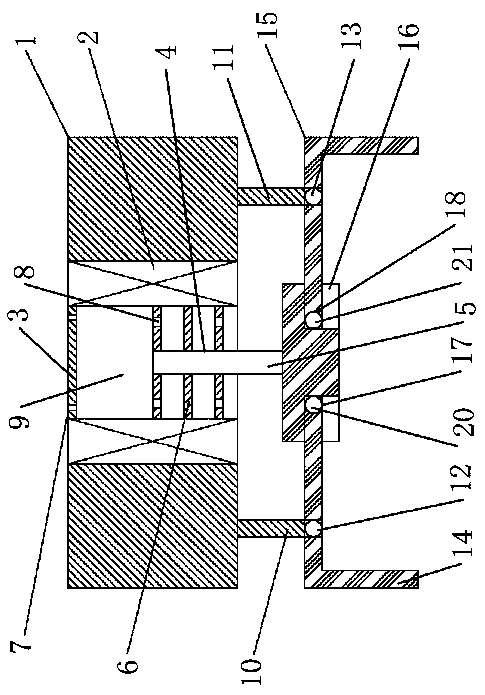
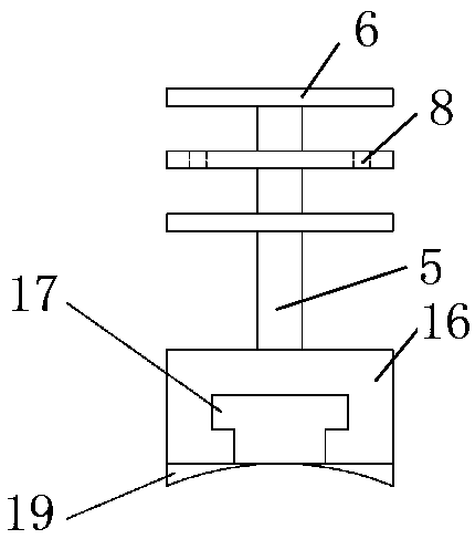
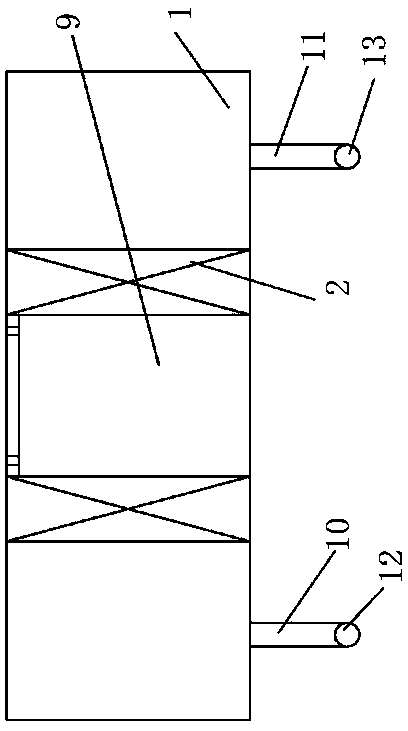
[0024] A magnetic fluid modular mechanical gripper, which consists of: a housing 1, the housing has a cylindrical cavity 9, a magnetic fluid is provided in the cylindrical cavity, and a top baffle is arranged in the cylindrical cavity 3 and a thin baffle plate 6, the thin baffle plate has a central hole 4, the central holes are connected by a vertical rod 5, and the top baffle plate has a group of ventilation holes 7 around the circumference. The thin baffle is provided with a group of liquid holes 8 around the circumference, and coils 2 are installed on both sides of the cylindrical cavity, and the coils are connected to the controller.

Embodiment 2

[0026] A magnetic fluid modular mechanical gripper described in Embodiment 1, the bottom of the housing is connected to the left straight rod 10 and the right straight rod 11, the left straight rod is connected to the left circular tube 12, and the right The straight rod is connected to the right circular pipe 13, the left circular pipe is hinged to the left actuator rod 14, the right circular pipe is hinged to the right actuator rod 15, and the left actuator rod and the right actuator rod are simultaneously Connect the lifting mechanism, the lifting mechanism includes the vertical bar, the vertical bar is connected to the rectangular block 16, the rectangular block has a left groove 17 and a right groove 18, the bottom of the rectangular block There is an arched surface 19, and the left groove and the right groove are connected to the arched surface.

Embodiment 3

[0028] In the magnetic fluid modular mechanical gripper described in Embodiment 2, the left actuator rod is connected to the left cylindrical bump 20, the right actuator rod is connected to the right cylindrical bump 21, and the left cylindrical bump 21 is connected to the left cylindrical bump. The block is installed in the left groove, and slides and rotates along the left groove, and the right cylindrical protrusion is installed in the right groove, and moves along the right groove Slide, rotate.


PUM


Abstract

The invention relates to a magnetic fluid modular mechanical gripper and a working method thereof; the composition of the product comprises a shell, wherein the shell is provided with a cylindrical cavity, magnetic fluid is arranged in the cylindrical cavity, a top baffle and thin baffles are arranged in the cylindrical cavity, central holes are formed in the thin baffles; the central holes are connected through a vertical rod; a group of vent holes are formed on the top baffle around the circumference; a group of liquid through holes are formed in the thin baffles around the circumference, coils are arranged at two side edges of the cylindrical cavity, and the coils are connected with a controller. The mechanical gripper provided by the invention is used for clamping small products such as batteries.

Description

Technical field: [0001] The invention relates to a magnetic fluid modular mechanical gripper and a working method. Background technique: [0002] Magnetic fluid is a colloidal dispersion system composed of base liquid and granular magnetic solid; the base liquid is the dispersion medium, generally kerosene and mechanical oil, etc., and the solid magnetic particles as the dispersed phase are usually ferromagnetic substances, such as iron , drill, nickel and their magnetic oxides, etc. Ferrofluids have colloidal stability and component stability, as well as good magnetization properties. When no external magnetic field is applied, the smaller the viscosity of the rheological fluid (≤1.0Pa·s), the better the magnetorheological effect of the rheological fluid. The viscosity of the magnetic fluid has a significant change after the magnetization, and the response is fast. At present, the saturation magnetization of ferrofluid with magnetite as solid particles can reach up to ab...

Claims


Application Information

Patent Timeline
Patent Type & Authority Applications(China)
IPC IPC(8): B25J15/00
Inventor 李增强王猛李沛然刘新华
Owner 哈工大机器人(山东)智能装备研究院
Why Eureka
Try Eureka