[0040] In the following, only certain exemplary embodiments are briefly described. As those skilled in the art can realize, the described embodiments may be modified in various different ways without departing from the spirit or scope of the present invention. Therefore, the drawings and descriptions are to be regarded as illustrative in nature and not restrictive.
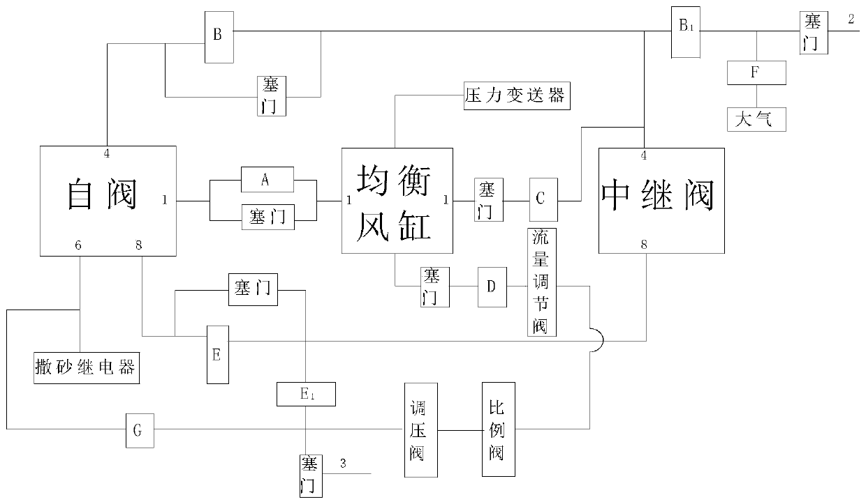
[0041] The present invention will be described in detail below with reference to the drawings. Such as figure 1 As shown, it shows the principle diagram of the self-valve remote control system of the JZ-7 series brake provided by the present invention. by figure 1 It can be seen that the self-valve remote control system of the JZ-7 series brake provided by the present invention includes: self-valve, equalizing air cylinder and relay valve, wherein a normally open is set on the equalizing air cylinder pipe between the self-valve and the equalizing air cylinder Solenoid valve A, the valve release position is that the balance air cylinder tube between the self valve and the balance air cylinder is connected, and the action position is that the balance air cylinder tube between the self valve and the balance air cylinder is cut off. A normally open solenoid valve B is set on the middle equalizing pipe between the self valve and the relay valve. The release position of the valve is that the middle equalizing pipe between the self valve and the relay valve is connected, and the action position is the self valve and the relay valve. The middle averaging pipe is cut off; a normally closed solenoid valve B1 is set between the middle averaging pipe at the relay valve end and the train pipe. The release position of the valve is to cut off the middle averaging pipe and the train pipe at the relay valve end, and the action position is middle The intermediate averaging pipe at the relay valve end communicates with the train pipe; a normally closed solenoid valve C is set between the equalizing cylinder pipe at the equalizing air cylinder end and the intermediate averaging pipe at the relay valve end, and the valve release position is the equalizing air cylinder at the equalizing air cylinder end The pipe is cut off from the intermediate pipe at the end of the relay valve, and the action position is that the equalizing cylinder pipe at the end of the equalizing cylinder communicates with the intermediate pipe at the end of the relay valve. A pressure regulating valve, a proportional valve, a flow regulating valve and a normally closed solenoid valve D are set between the main air cylinder pipe and the equalizing air cylinder pipe. It takes time for the flow regulating valve to adjust to the pressure of the equalizing air cylinder to 140kPa (or 170kPa) during installation. 4-7 seconds; the function of the pressure regulating valve is to adjust the pressure of the total air cylinder to the rated working air pressure of the proportional valve; the proportional valve is a product that can output 0-600kPa air pressure in equal proportions according to the control analog signal. A pressure transmitter is provided on the equalizing air cylinder. A normally open solenoid valve E is set between the self-valve and the main air interruption pipe of the relay valve. The valve release position is that the self valve communicates with the main air interruption pipe of the relay valve, and the action position is the self-valve Cut off with the main air cutoff pipe of the relay valve; a normally closed solenoid valve E1 is arranged between the main air cutoff pipe and the main air cylinder pipe at the relay valve end, and the release position of the valve is the total air flow at the relay valve end. The interrupting pipe is cut off from the main air cylinder pipe, and the action position is that the main air interrupting pipe at the relay valve end communicates with the main air cylinder pipe; an electric air release solenoid valve F is installed on the train pipe. A normally closed solenoid valve G is set between the main air cylinder pipe and the sanding relay.
[0042] According to a preferred embodiment of the present invention, in order to prevent the failure of the solenoid valve from affecting the braking of the locomotive, a faulty plug can be installed on the solenoid valve. The normally closed solenoid valve C, D, the main air cylinder pipe and the train pipe are connected in series with the plug door. Open solenoid valves A, B and E in parallel with the plugs. Once the solenoid valve fails, the plug can be used to cut off the solenoid valve, and the locomotive will be manually controlled.
[0043] When the JZ-7 series brake machine self-valve remote control system provided by the present invention is used for operation, an embodiment of the present invention also provides the following method:
[0044] When manually operated (without remote control), the self-valve remote control system is powered off, the solenoid valve A is in the release position, and the balancing cylinder pipe between the self-valve and the balancing cylinder is connected; the solenoid valve B is the release position, and the self-valve and relay The middle averaging pipes between the valves are connected; the solenoid valve B1 is the release position, the middle averaging pipe at the relay valve end is cut off from the train pipe; the solenoid valve C is the release position, the balancing air cylinder pipe at the balance air cylinder end and the middle averaging pipe at the relay valve end Shut off; Solenoid valve D closes and cuts off the proportional valve path; solenoid valve E is the release position, the relay valve's main air interruption pipe is connected to the self valve; solenoid valve E1 is the release position, the relay valve end of the main air interruption pipe and the main air cylinder The pipe is cut off; the electric vent valve F is closed; the solenoid valve G is closed, cutting off the passage between the main air cylinder pipe and the sanding relay; the locomotive brake is controlled by the original brake.
[0045] When remote control, put the valve in the operating position:
[0046] For example, when the remote control locomotive is relieved, the solenoid valve A is the action position, and the equalizing air cylinder tube between the self valve and the equalizing air cylinder is cut off; the solenoid valve B is the action position, and the middle equalizing pipe between the self valve and the relay valve is cut off; Valve E is the release position, the main air interruption pipe of the relay valve is communicated with the self-valve; the solenoid valve B1 is the release position, and the intermediate pipe at the relay valve end is cut off from the train pipe; the solenoid valve C is the action position to balance the balance of the air cylinder end The air cylinder pipe communicates with the middle pipe at the relay valve end; the electric air discharge solenoid valve F is closed; the solenoid valve G is closed, cutting off the passage between the main air cylinder pipe and the sanding relay; the solenoid valve E1 release position, the main air cylinder pipe and the middle The relay valve's total air interruption pipe is cut off; the solenoid valve D is opened, the remote control system issues a relief command, and receives the analog signal from the microcomputer to control the proportional valve to charge the balance air cylinder, and the balance air cylinder returns to a constant pressure. The balance air cylinder passes through solenoid valves C, The intermediate pipe control relay valve is relieved, and the locomotive is under the control of the relay valve and the locomotive automatically resumes the constant pressure train to relieve.
[0047] For example, when the remote control locomotive is frequently braking, the solenoid valve A is the action position, and the equalizing air cylinder tube between the self valve and the equalizing air cylinder is cut off; the solenoid valve B is the action position, and the intermediate pipe between the self valve and the relay valve is cut off; Solenoid valve B1 is the release position, the intermediate pipe at the relay valve end is cut off from the train pipe; solenoid valve C is the action position, the equalizing cylinder pipe at the equalizing air cylinder end communicates with the intermediate pipe at the relay valve end; the solenoid valve E is the action position , The main air blocking pipe of the relay valve is cut off from the self-valve; the solenoid valve E1 is the action position, the main air blocking pipe at the relay valve end is connected to the main air cylinder pipe; the electric air release valve F is closed; the solenoid valve G is closed; the solenoid valve D Turn on, the remote control system receives the microcomputer to control the proportional valve to decompress, the equalizing air cylinder begins to reduce the pressure to the control pressure, the pressure change of the equalizing air cylinder is reflected to the relay valve through the solenoid valve C and the intermediate pipe of the relay valve, and the train pipe is reduced accordingly. Pressure, the train brakes.
[0048] For example, during emergency braking of a remote control locomotive, solenoid valve A is the action position, and the equalizing air cylinder tube between the self valve and the equalizing air cylinder is cut off; solenoid valve B is the action position, and the middle equal pipe between the self valve and the relay valve is cut off; Solenoid valve B1 is the action position, the middle averaging pipe at the relay valve end is connected to the train pipe to protect the relay valve diaphragm; solenoid valve C is the release position, the balancing air cylinder pipe at the balance air cylinder end and the middle averaging pipe at the relay valve end are cut off ; Solenoid valve D is opened, the remote control system sends out a pressure reduction command, and receives the analog signal output by the microcomputer to control the proportional valve to reduce the pressure of the equalizing air cylinder by 240-260kPa; the solenoid valve E is the action position, and the relay valve's main air blocking pipe is cut off from the self valve ; Solenoid valve E1 is the action position, the main air blocking pipe at the relay valve end is connected to the main air cylinder pipe; the electric air release valve F opens the train pipe and quickly drops to 0, the locomotive brakes emergency; at the same time the solenoid valve G opens for emergency sanding.
[0049] Finally, it should be noted that the above descriptions are only preferred embodiments of the present invention and are not intended to limit the present invention. Although the present invention has been described in detail with reference to the foregoing embodiments, it is still for those skilled in the art. The technical solutions described in the foregoing embodiments may be modified, or some of the technical features may be equivalently replaced. Any modification, equivalent replacement, improvement, etc., made within the spirit and principle of the present invention shall be included in the protection scope of the present invention.