Variable cross-section spiral drilling tool and construction method of variable cross-section cast-in-situ bored pile

A technology of variable cross-section and helical drill rods, which is applied in the direction of drilling equipment and methods, rotary drilling, rotary drilling rigs, etc., which can solve the problems of inability to achieve reaming, inconvenient construction, and inability to open the drill tip, etc., to achieve increased connection , improve the service life and reduce the effect of rotating torque

Pending Publication Date: 2019-05-10
JIANGSU DONGHENAN GEOTECHNICAL TECH CO LTD
View PDF0 Cites 7 Cited by
  • Summary
  • Abstract
  • Description
  • Claims
  • Application Information

AI Technical Summary

Problems solved by technology

By applying tension to the steel cable, the drill tip at the lower end is used to ream the hole. However, due to the complex geological conditions of the foundation and the extensibility of one end of the steel cable, it often happens that the drill tip cannot be opened, which makes the hole reaming impossible. cause great inconvenience

Method used


Image

  • Variable cross-section spiral drilling tool and construction method of variable cross-section cast-in-situ bored pile
  • Variable cross-section spiral drilling tool and construction method of variable cross-section cast-in-situ bored pile
  • Variable cross-section spiral drilling tool and construction method of variable cross-section cast-in-situ bored pile

Examples


Embodiment 1

[0035] In this embodiment, a further description is made on the variable-section auger.

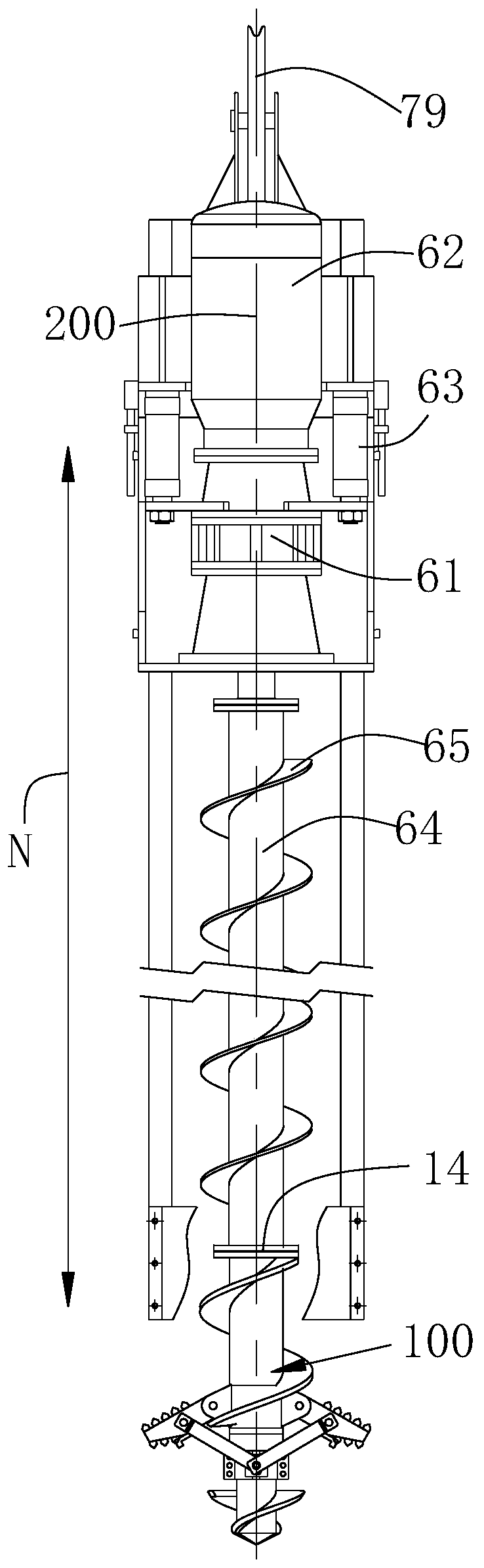
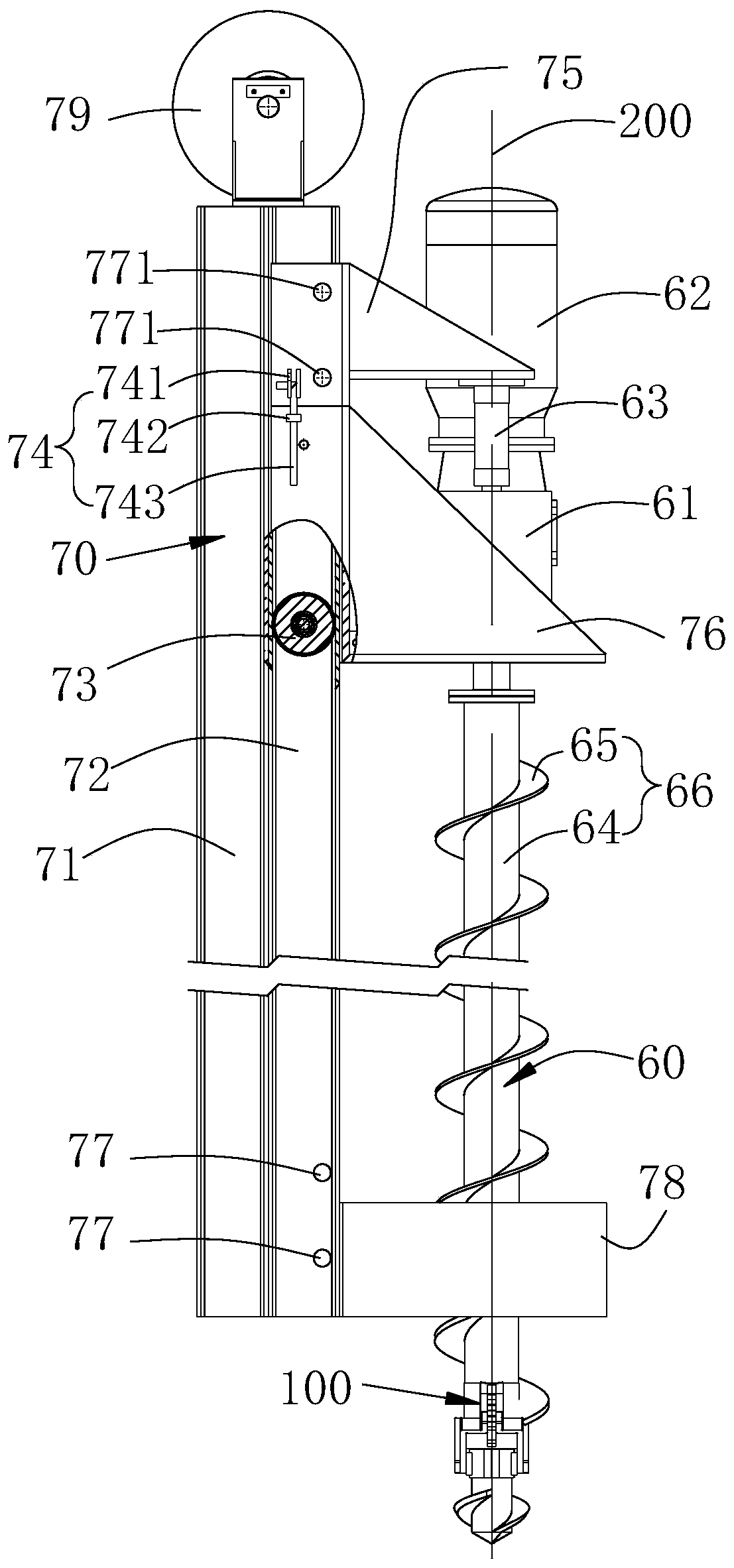
[0036] see figure 1 and figure 2 , is a specific embodiment of a variable cross-section auger, which includes a guide device 70 and an auger rod 60 installed on the guide device 70, the auger rod 60 has a central axis 200, and the central axis 200 is parallel to an axis N, the guide device 70 includes a guide frame 71 and a guide rail 72 installed on the guide frame 71 .

[0037] The auger rod 60 includes a helical rod 66 and a drill head 100 mounted on the bottom end of the auger rod. The auger rod 66 has a central rod 64 and a helical blade 65 spirally surrounding the central rod 64 . In this embodiment, the central rod 64 is a hollow rod.

[0038] see Figure 3-Figure 6 The drill head 100 includes an outer sleeve 11 , a guide rod 21 , a connecting rod 37 and an enlarged head blade 30 , and one end of the outer sleeve 11 is fixedly installed on the bottom end of the screw rod throu...

Embodiment 2

[0062] In this embodiment, the construction method of the bored pile is further described. In this embodiment, the variable-section helical drilling tool in Embodiment 1 is used. In this embodiment, the same reference numerals as in Embodiment 1 represent the same technical features.

[0063] This construction method comprises the steps:

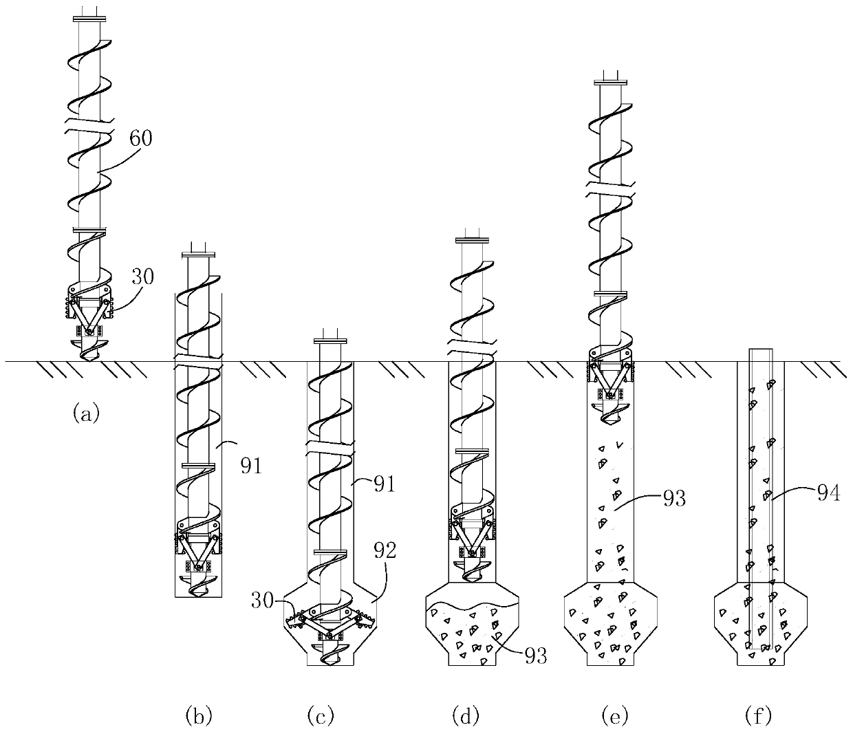
[0064] (1) Please refer to Figure 7 In steps (a) and (b), install the guide device of the variable-section auger to the set position, make the expanding head blade 30 in the retracted position, start the drive motor, and make the auger rod 60 rotate forward and move along the set position. Drill out the main pile hole 91 in the direction;

[0065] (2) See Figure 7 In step (c), the height position of the auger drill rod 60 is maintained, the clamping part is fixedly connected to the limit part, the limit part is fixed on the guide device, and then the auger drill rod is reversed, and the auger drill rod is at the original depth Rotate, ...


PUM


Abstract

The invention discloses a variable cross-section spiral drilling tool which comprises a guiding device and a spiral drilling rod installed on the guiding device, the spiral drilling rod comprises a spiral rod and a drill bit portion installed at the bottom end, the drill bit portion comprises an outer sleeve, a guiding rod, a connecting rod and an expanding head blade, and one end of the outer sleeve is fixedly installed at the bottom end of the spiral rod; the guide rod is sleeved by the outer sleeve, and one end of the guide rod extends out of the outer sleeve to form a drill bit; one end ofthe expanding head blade is hinged to the outer sleeve, one end of the connecting rod is hinged to the guide rod, and the other end of the connecting rod is hinged to the expanding head blade; and when the guiding rod moves along the axis direction, the expanding head blade is unfolded or folded. The invention further discloses a construction method for a variable cross-section cast-in-situ boredpile by utilizing the variable cross-section spiral drilling tool. The drilling tool integrates high efficiency and rapidness, integrates drilling, chambering, pouring and detection, and has good operation performance. The construction method has the advantages of high efficiency and high construction precision.

Description

technical field [0001] The invention relates to the field of building construction, in particular to a variable-section helical drilling tool and a construction method for variable-section bored piles. Background technique [0002] At present, most buildings adopt reinforced concrete cast-in-place piles, mostly equal-section straight-hole cast-in-place piles. In pile foundation design, the method of increasing the diameter and length of the pile is mostly used to increase the friction between the pile and the soil. However, this method does not make full use of the strength of the pile body, which not only costs high, but also wastes materials. Therefore, it is a commonly used method in construction to use bottom reaming drill bits to ream the holes during the hole forming process, so as to appropriately expand the bottom of the pile holes and increase the pile bearing capacity. Bottom expansion piles mainly include bored bottom expansion piles, rotary expansion piles and s...

Claims


Application Information

Patent Timeline
Patent Type & Authority Applications(China)
IPC IPC(8): E21B10/44E21B10/32E21B17/22E21B7/28E21B3/02E21B19/24E02D5/34E02D5/36
Inventor 王涛李仁民杨东升王建兰刘飞
Owner JIANGSU DONGHENAN GEOTECHNICAL TECH CO LTD
Why Eureka
Try Eureka