Draught fan and air conditioner with draught fan

A technology for air conditioners and fans, applied in air conditioning systems, machines/engines, household appliances, etc., to achieve the effect of compact overall structure, preventing incomplete vaporization, and low resistance

Pending Publication Date: 2019-05-10
GREE ELECTRIC APPLIANCES INC
View PDF0 Cites 3 Cited by
  • Summary
  • Abstract
  • Description
  • Claims
  • Application Information

AI Technical Summary

Problems solved by technology

[0004] Therefore, the technical problem to be solved by the present invention is to overcome the defect that the fans in the prior art cannot vaporize the liquid droplets well to incr

Method used


Image

  • Draught fan and air conditioner with draught fan
  • Draught fan and air conditioner with draught fan
  • Draught fan and air conditioner with draught fan

Examples


Embodiment 1

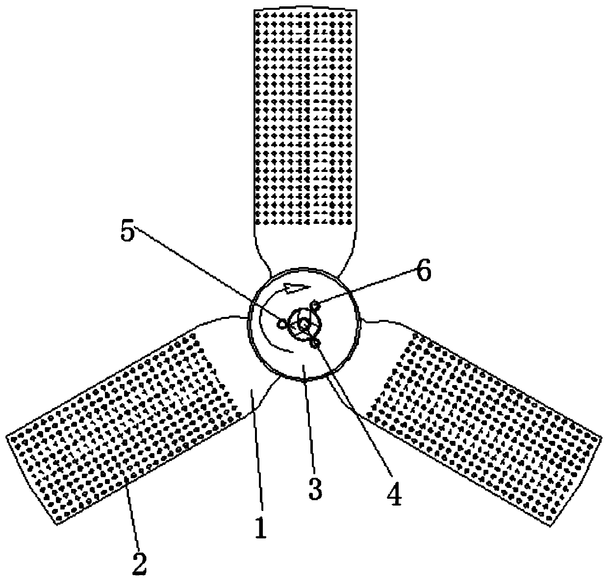
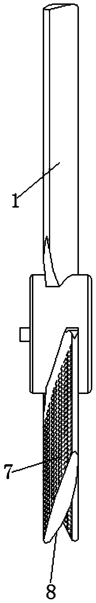
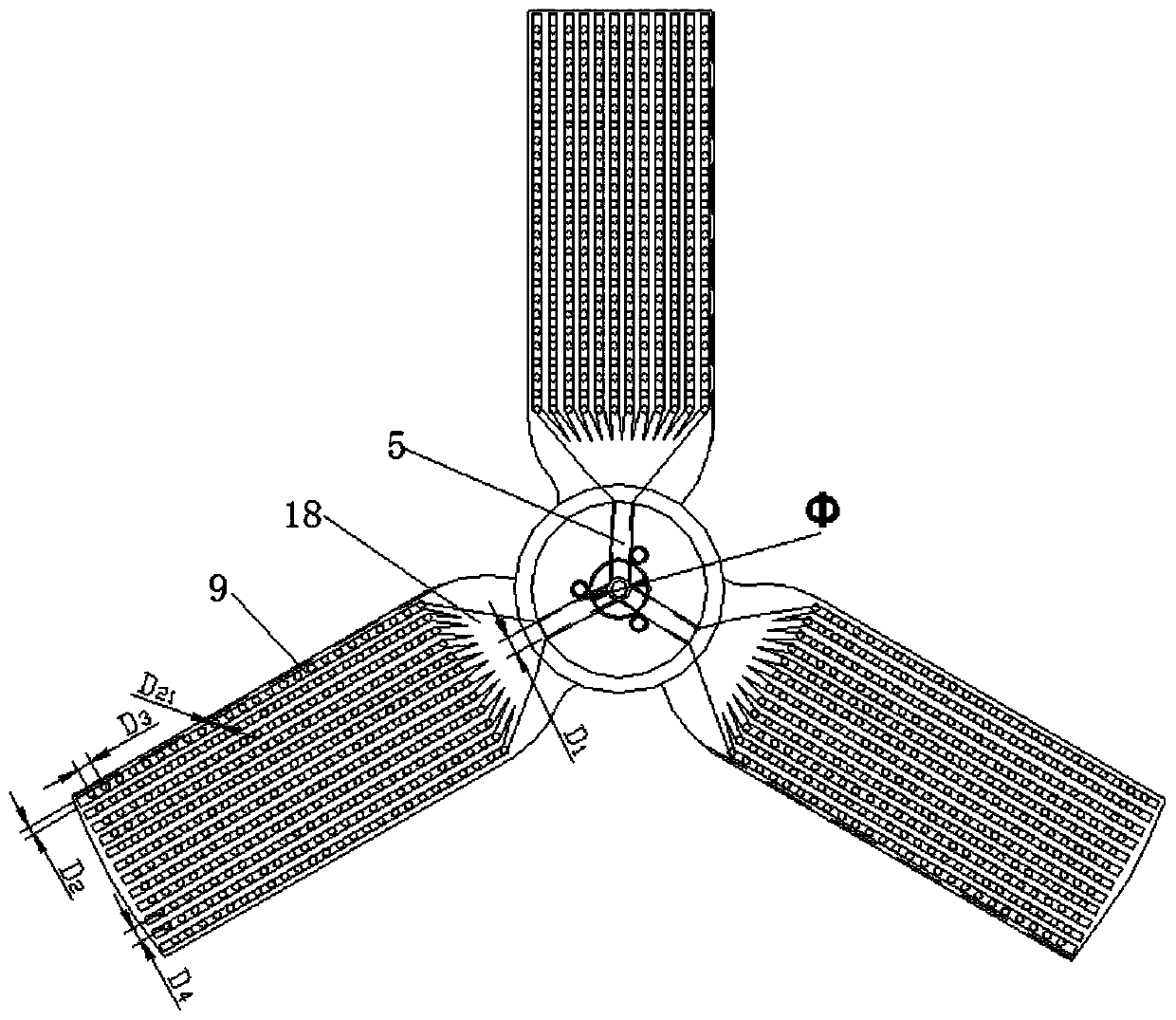
[0049] like figure 1 - image 3 As shown, this embodiment provides a fan, including: a rotating body 3 , blades 1 , microporous channels 9 and air holes 2 .

[0050] Blades 1, at least two, are arranged on the rotating main body 3; the microporous flow channel 9 is arranged inside the blade 1, and during the rotation of the blade 1, the microporous flow channel 9 is connected with the water source; the vent hole 2 is arranged on the blade The suction surface 7 of 1 communicates with the micropore flow channel 9. The suction surface 7 of the blade 1 is the side where the peripheral airflow pressure of the blade 1 is lower than the atmospheric pressure during the rotation process. The vent hole 2 introduces the negative pressure into the micropore flow channel 9 Inside, the vaporization of water in the microporous channel 9 is accelerated, and the vaporized water vapor is sent out by the rotating blade 1 .

[0051] By setting the microporous flow channel 9 connected to the wat...

Embodiment 2

[0068] like Image 6 - Figure 10 As shown, the difference between this embodiment and embodiment 1 is:

[0069] The fan in this embodiment is a centrifugal fan. As an alternative embodiment, it is also possible that the fan is a cross-flow fan.

[0070] The rotating main body 3 of the blower fan in this embodiment includes a top plate 11 and a chassis 12, the blade 1 is connected between the top plate 11 and the bottom plate 12, the top plate 11 is an annular structure, and the top plate 11 is provided with an inner cavity 10, and The cavity 10 is in communication with the microporous flow channel 9 on each blade 1 , and also includes a water supply main pipe 4 in communication with the inner cavity 10 . Specifically, the inner cavity 10 in this embodiment is a hollow water separator.

[0071] Specifically, the main water supply pipe 4 in this embodiment is arranged at the center of the top plate 11, and the main water supply pipe 4 communicates with the inner cavity 10 t...


PUM

PropertyMeasurementUnit
The inside diameter ofaaaaaaaaaa

Abstract

The invention relates to the technical field of air conditioners, in particular to a draught fan and an air conditioner with the draught fan. The draught fan comprises a rotating body, at least two blades arranged on the rotating body, microhole runners arranged in the blades and communicating with water sources in the blade rotating process, and ventilation holes formed in the force suction facesof the blades and communicating with the microhole runners, wherein the force suction faces of the blades are the faces, of which the peripheral air flow pressure is lower than the atmospheric pressure, of the blades in the rotating process, the ventilation holes are used for introducing the negative pressure into the microhole runners to accelerate vaporization of water in the microhole runners,and the vaporized vapor is sent out through the rotating blades. Due to the fact that the microhole runners are arranged in the blades of the draught fan, due to gravity or centrifugal force generated by blade rotating, feeding of water in the microhole runners in the blades is achieved; and due to the fact that the ventilation holes are formed in the force suction faces of the blades, the ventilation holes are used for introducing the negative pressure into the microhole runners, and therefore vaporization of water in the microhole runners is accelerated, and the moisture content of the airis rapidly increased.

Description

technical field [0001] The invention relates to the technical field of air conditioning, in particular to a blower fan and an air conditioner equipped with it. Background technique [0002] As the seasons change, the air humidity in autumn and winter decreases sharply, seriously affecting people's living comfort. For humidifiers currently on the market, the humidification method is generally selected from the following two methods: ① use electric heating to increase the moisture content of the air; ② use water-absorbing and atomizing parts to force the circulating air to pass through the parts Forced humidification. However, these two humidification methods do not meet the increasingly stringent environmental protection requirements, and cannot make good use of energy. Method 1 uses electric heating. The additional heat has no other value except to increase the moisture content of the air, and may even affect the user's comfort experience. The second method needs to drive...

Claims


Application Information

Patent Timeline
IPC IPC(8): F04D29/32F04D29/38F04D29/28F04D29/26F04D29/30F24F1/0018F24F13/22
Inventor 朱芳勇王现林吴俊鸿高旭陈志伟赖孝成陶梦春廖俊杰李树云李建建
Owner GREE ELECTRIC APPLIANCES INC
Why Eureka
Try Eureka