
Gas-liquid two-phase mass flowmeter

A mass flow meter, mass flow technology, applied in the direction of indirect mass flow meter, mass flow measurement device, volume flow measurement device, etc. Large and other problems, to achieve the effect of improving the measurement range and adaptability, and ensuring the reliability of work

Pending Publication Date: 2019-05-10
XINJIANG ZHONGYUAN TIANNENG OIL & GAS TECH CO LTD
View PDF0 Cites 2 Cited by
  • Summary
  • Abstract
  • Description
  • Claims
  • Application Information

AI Technical Summary

Problems solved by technology

[0003] At present, the traditional mass flowmeter can only use gas phase or liquid phase (single phase) as the measurement medium. If the volume percentage of the gas phase in the liquid phase exceeds 5% to 10%, the mass flowmeter will drive abnormally, stop or restart , the noise becomes louder, and the vibration frequency is out of control, resulting in a large error or unable to measure
[0004] In addition, when the mass flowmeter is used to measure the gas-liquid two-phase flow, there is still a problem: the lower limit flow measurement value is relatively high, and the gas-liquid ratio and flow fluctuation are the normal working conditions of the gas-liquid two-phase flow. The mass flowmeter will increase the measurement error of the gas-liquid two-phase flow and the measurement result of the small flow rate will be zero. The above problems greatly limit the wide application of the mass flowmeter to measure the gas-liquid two-phase flow

Method used


Image

  • Gas-liquid two-phase mass flowmeter
  • Gas-liquid two-phase mass flowmeter
  • Gas-liquid two-phase mass flowmeter

Examples


Embodiment Construction

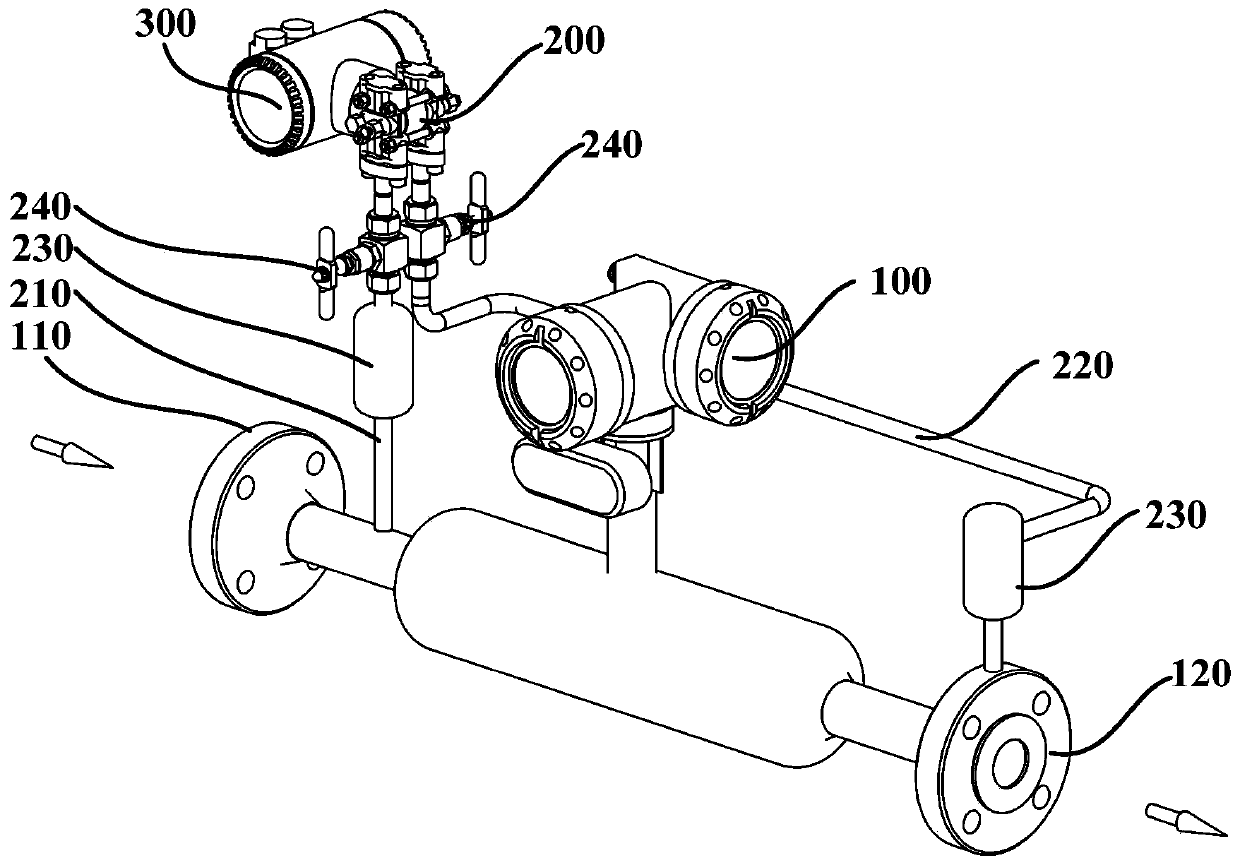
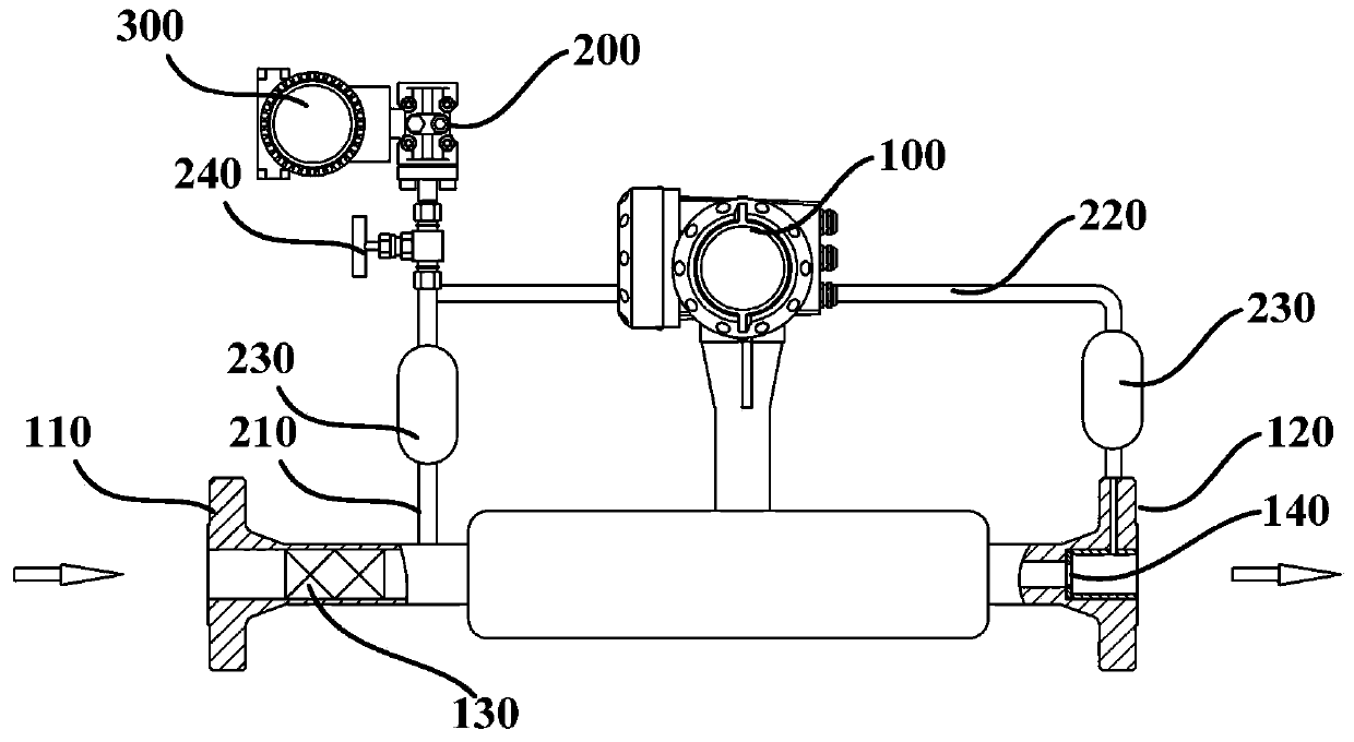
[0027] figure 1 is a schematic structural diagram of a gas-liquid two-phase mass flowmeter according to an embodiment of the present invention. figure 2 is based on figure 1 Schematic of another angle of the gas-liquid two-phase mass flowmeter shown.

[0028] The gas-liquid two-phase mass flowmeter of this embodiment may generally include: a mass flowmeter 100 , a pressure differential pressure composite sensor 200 , and a flow computer 300 .

[0029] The mass flow meter 100 is connected to the pipeline of the measured gas-liquid two-phase fluid, and is used to measure the temperature, mass flow rate and mixed density of the measured gas-liquid two-phase fluid.

[0030] The pressure differential pressure composite sensor 200, its differential pressure positive pressure pipe 210 and differential pressure negative pressure pipe 220 are respectively connected to the upstream pipeline and the downstream pipeline of the mass flow meter 100, and are used to measure the measured g...


PUM


Abstract

The invention provides a gas-liquid two-phase mass flowmeter. The gas-liquid two-phase mass flowmeter comprises a mass flowmeter, a differential pressure composite sensor and a flow computer, whereinthe mass flowmeter is used for measuring a mass flow, a temperature and a mixing density of a tested gas-liquid two-phase fluid; a differential pressure positive pressure pipe and a differential pressure negative pressure pipe of the differential pressure composite sensor are respectively connected with a pipeline, flowing to downstream and a pipeline, flowing to upstream, of the mass flowmeter; the differential pressure composite sensor is used for measuring average pressure and differential pressure of the tested gas-liquid two-phase fluid before and after flowing through the mass flowmeter;and the flow computer is connected with each of the mass flowmeter and the pressure differential composite sensor, and is used for calculating a gas-liquid two-phase flow of the tested gas-liquid two-phase fluid by combining a database in the mass flowmeter according to measurement parameters of the mass flowmeter and the differential pressure composite sensor, external input liquid-phase densityand gas-phase density. The gas-liquid two-phase mass flowmeter can be applied to condensate natural gas wells, aqueous shale gas wells, oil wells and other fields of multi-phase flow measurement, andthe measurement range and adaptability of the gas-liquid two-phase mass flowmeter are improved.

Description

technical field [0001] The invention relates to industrial multiphase flow measurement, in particular to a gas-liquid two-phase mass flowmeter. Background technique [0002] As a flowmeter with excellent performance and high precision, mass flowmeter has been widely used in gas and liquid flow measurement in industrial fields. [0003] At present, the traditional mass flowmeter can only use gas phase or liquid phase (single phase) as the measurement medium. If the volume percentage of the gas phase in the liquid phase exceeds 5% to 10%, the mass flowmeter will drive abnormally, stop or restart , the noise becomes larger, and the vibration frequency is out of control, resulting in large errors or inability to measure. [0004] In addition, when the mass flowmeter is used to measure the gas-liquid two-phase flow, there is another problem: the lower limit flow measurement value is relatively high, and the gas-liquid ratio and flow fluctuation are the normal working conditions ...

Claims


Application Information

Patent Timeline
Patent Type & Authority Applications(China)
IPC IPC(8): G01F1/88G01F7/00
Inventor 卢玖庆何峰王良贵何宇王彬臣高永鑫施斌
Owner XINJIANG ZHONGYUAN TIANNENG OIL & GAS TECH CO LTD
Learn More