A PWM output driving IO circuit used for eliminating peak current

A technology of output drive and peak current, which is applied in the field of IO circuits, can solve the problems affecting the normal operation of the power supply part in the system and easily damaged drive devices, etc., and achieve the effect of meeting bandwidth requirements and flexible adaptability

Active Publication Date: 2019-05-10
苏州睿晟芯微电子科技有限公司
View PDF4 Cites 4 Cited by
  • Summary
  • Abstract
  • Description
  • Claims
  • Application Information

AI Technical Summary

Problems solved by technology

[0007] Although some methods are used in some circuits to prevent the PMOS and NMOS transistors in the drive tube from being turned on at the same time, a very large peak current is generated at the moment of the output pulse reversal, which is very easy to damage the drive device of the circuit and even affect the system. The power supply works normally

Method used


Image

  • A PWM output driving IO circuit used for eliminating peak current
  • A PWM output driving IO circuit used for eliminating peak current
  • A PWM output driving IO circuit used for eliminating peak current

Examples


Embodiment Construction

[0053] In order to enable those skilled in the art to better understand the technical solutions in the present invention, the technical solutions in the embodiments of the present invention will be clearly and completely described below in conjunction with the drawings in the embodiments of the present invention. Obviously, the described The embodiments are only some of the embodiments of the present invention, not all of them. Based on the embodiments of the present invention, all other embodiments obtained by persons of ordinary skill in the art without making creative efforts shall fall within the protection scope of the present invention.

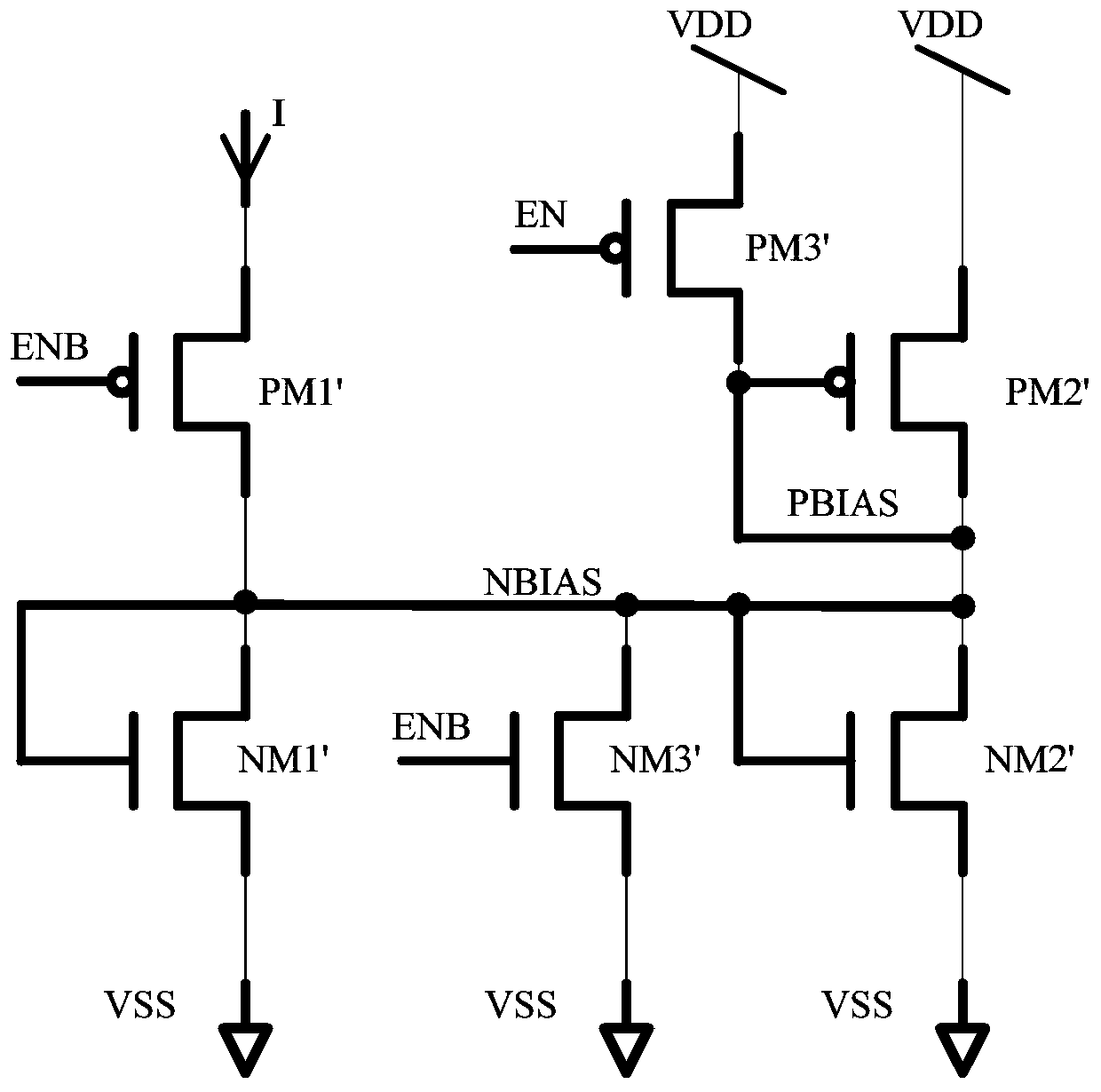
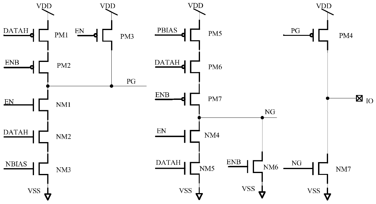
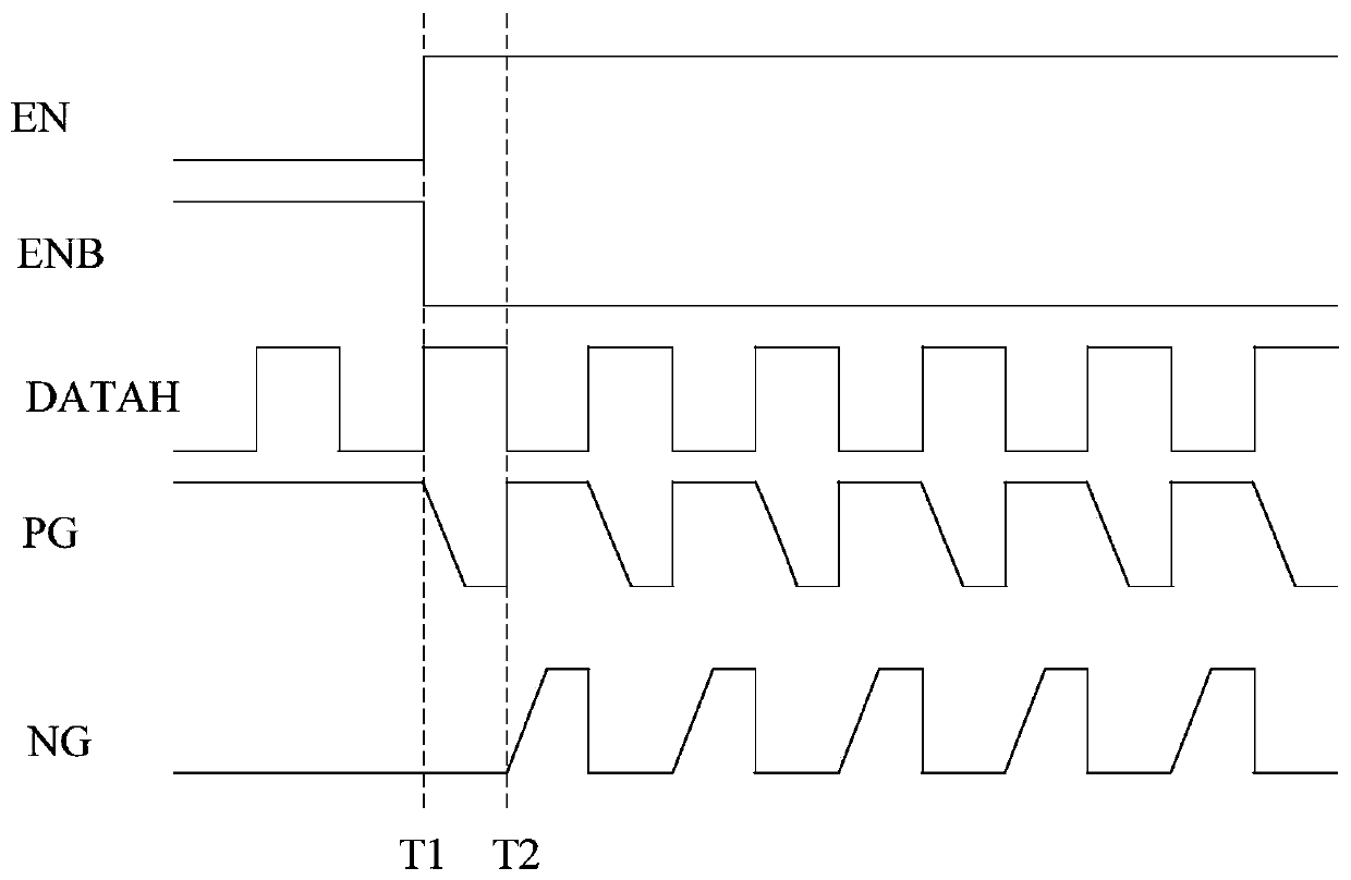
[0054] The invention utilizes constant bias current charging and discharging to control the grid voltage design of PMOS and NMOS tubes, which can effectively eliminate the peak currents of driving PMOS and NMOS tubes at the moment of turning on respectively, reduce chip area overhead and improve PWM output driving IO circuits speed.

...


PUM


Abstract

The invention discloses a PWM output driving IO circuit used for eliminating peak current. The IO circuit comprises a fourth PMOS transistor and a seventh NMOS transistor, the fourth PMOS transistor is connected between a circuit power supply voltage VDD and an IO interface, and the seventh NMOS transistor is connected between a circuit ground potential VSS and the IO interface. The first grid driving unit is used for driving a grid signal PG of the fourth PMOS transistor, and the first driving unit comprises a plurality of PMOS transistors and NMOS transistors which are connected between a circuit power supply voltage VDD and a circuit ground potential VSS; And the second grid driving unit is used for driving a grid signal NG of the seventh NMOS tube, and comprises a plurality of PMOS tubes and NMOS tubes which are connected between a circuit power supply voltage VDD and a circuit ground potential VSS. The IO circuit has the advantages of being simple in structure, easy to integrate,flexible, adaptive, capable of achieving self-electrostatic protection and the like.

Description

technical field [0001] The invention relates to the technical field of IO circuits, in particular to a PWM output driving IO circuit for eliminating peak current. Background technique [0002] PWM output is pulse width modulation output. PWM output drive IO circuits are commonly found in digital-analog hybrid chips, MCU, SOC and other systems. Most systems drive peripheral LED displays, motors and other devices. Because these devices are driven by current, there are tens of mA or even hundreds of mA of drive capability on the market. [0003] ginseng figure 1 Shown is a circuit diagram for generating bias current in the prior art, NMOS tubes include NM1', NM2', NM3', and PMOS tubes include PM1', PM2', PM3', where: [0004] PM1' is used to control the external bias current input. When the enable signal EN is VDD and ENB is VSS, the bias current input is accepted, otherwise the bias current input is cut off; [0005] NM1', NM2', PM2' are used to generate mirror bias current...

Claims


Application Information

Patent Timeline
IPC IPC(8): H03K5/04H03K19/003
CPCY02B70/10
Inventor 不公告发明人
Owner 苏州睿晟芯微电子科技有限公司
Why Eureka
Try Eureka