Driving control circuit and household appliance

A drive control circuit and control terminal technology, applied in the field of circuits, can solve problems such as improving thermal crosstalk of drive control circuits, increasing power consumption of drive control circuits, and affecting reliability of local devices, etc., achieving low power consumption, reduced leakage, and long working hours Effect

Pending Publication Date: 2019-05-10
GD MIDEA AIR-CONDITIONING EQUIP CO LTD
View PDF0 Cites 8 Cited by
  • Summary
  • Abstract
  • Description
  • Claims
  • Application Information

AI Technical Summary

Problems solved by technology

[0005] (1) Since it is necessary to continuously power on to control the power supply state of the drive control circuit, it will increase the power consumption of the drive control circuit
[0006] (2) Since the load on the relay is usually an AC signal with a frequency of 50Hz and an effective value of 220V, there is a risk of leakage if the relay is continuously energized
[0007] (3) If the relay is frequently powered on and off, interference pulses such as surge signals and ripple signals will appear in the drive control circuit, which will cause some components in the drive control circuit to heat up sharply, and even be burned, which will not only affect the reliability of local devices, but also increase the thermal crosstalk in the drive control circuit

Method used


Image

  • Driving control circuit and household appliance
  • Driving control circuit and household appliance
  • Driving control circuit and household appliance

Examples


Embodiment 1

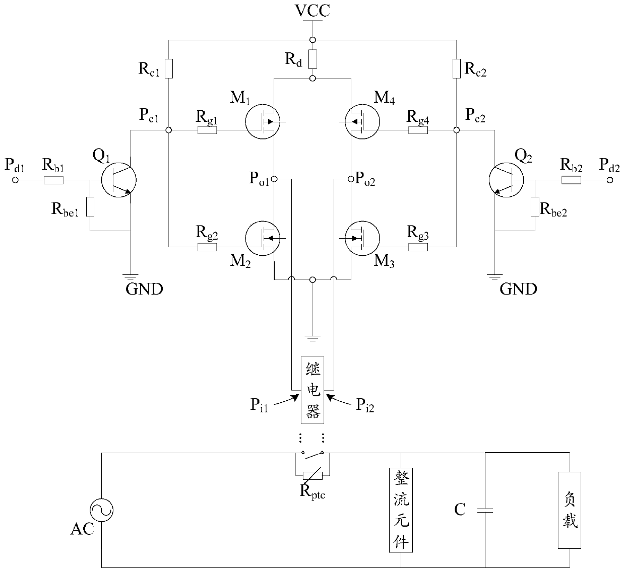
[0085] Such as figure 2 As shown, according to the driving control circuit of the above-mentioned embodiment of the present invention, preferably, the first current limiting resistor is R connected in series between the bridge circuit and the DC source VCC d , used for current limiting protection of the bridge circuit.

Embodiment 2

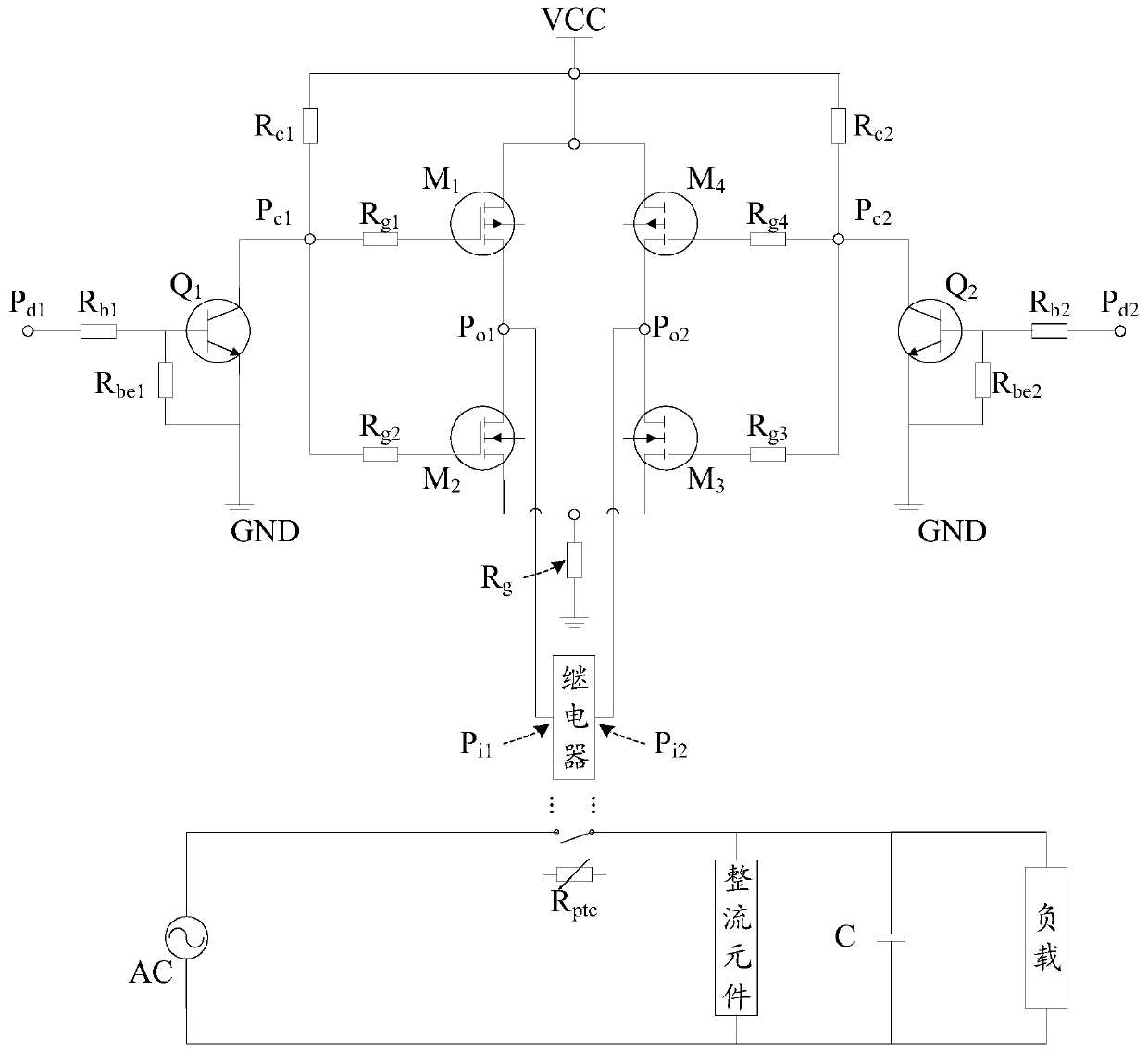
[0087] Such as image 3 As shown, according to the driving control circuit of the above-mentioned embodiment of the present invention, preferably, the first current limiting resistor is R connected in series between the bridge circuit and the ground wire GND g , used for current limiting protection of the bridge circuit.

[0088] According to the drive control circuit of the embodiment of the present invention, the current limiting protection of the bridge circuit is performed by setting the first current limiting resistor. On the one hand, it is beneficial to reduce the impact of the overcurrent signal in the AC of the grid system on the bridge circuit. , when any bridge arm in the bridge circuit has a short-circuit fault, the impact of the short-circuit current switching unit can be reduced.

[0089] For example, if the first bridge arm and the second bridge arm are turned on at the same time, and there is no current limiting resistor connected in series with the two bridge...

Embodiment 3

[0103] Such as Figure 4 As shown, the switching tube M of the first bridge arm 1 It is a P-type MOSFET, the switch tube M of the second bridge arm 2 It is an N-type MOSFET, and the switching tube M of the fourth bridge arm 4 It is a P-type MOSFET, and the switch tube M of the third bridge arm 3 For N-type MOSFETs, a first current limiting resistor R s1 connected to the switch tube M 1 The source and switch tube M 2 between the drains, another second current limiting resistor R s2 connected to the switch tube M 4 The source and switch tube M 3 between the drain electrodes.


PUM


Abstract

The invention provides a drive control circuit and a household appliance, the drive control circuit comprises a self-holding relay, whereina moving contact of the self-holding relay is connected to apower grid system, and the power grid system can be controlled to supply power to a load; a Bridge circuit, wherein The bridge circuit is configured to output a pulse signal to the control end of theself-hold relay, the pulse signal is a high-level pulse signal or a low-level pulse signal; wherein the first control end of the self-hold relay receives a high-level pulse signal; Meanwhile, when thesecond control end of the self-holding relay receives the low-level pulse signal, the moving contact of the self-holding relay performs action switching, and keeps the state after the previous actionswitching before receiving the next pulse signal, and the action switching is switched from the closing state to the opening state or from the opening state to the closing state. Through the technical scheme of the invention, the power consumption of the driving control circuit is reduced, and meanwhile, the damage risk caused by electric leakage and device temperature rise is reduced, so that the service life is prolonged.

Description

technical field [0001] The present invention relates to the technical field of circuits, in particular, to a drive control circuit and a household electrical appliance. Background technique [0002] As a control component, the relay is widely used in the drive control circuit, and plays the role of automatic adjustment, safety protection, conversion circuit, etc. [0003] For example, in the drive control circuit of the outdoor unit of the inverter air-conditioning system, in order to avoid the excessive input AC current impacting the capacitance when the power is turned on, the traditional relay is often used to limit the charging current, that is, the drive is changed by controlling the power on or off of the relay. Controls the power status of the circuit. [0004] In related technologies, the traditional relay is in a closed state when the control circuit is working, that is, it needs to be continuously powered on, which has at least the following technical problems: ...

Claims


Application Information

Patent Timeline
Patent Type & Authority Applications(China)
IPC IPC(8): H03K17/51H03K17/60H03K17/687
CPCH03K17/687H03K17/60H03K17/51
Inventor 邱禹文先仕曾贤杰黄招彬
Owner GD MIDEA AIR-CONDITIONING EQUIP CO LTD
Why Eureka
Try Eureka