Ultrasonic image probe cleaning device

A cleaning device and ultrasonic imaging technology, applied to water supply devices, cleaning methods and utensils, cleaning methods using liquids, etc., can solve the problems of low medical efficiency, poor wiping effect, cumbersome operation of manual wiping probes, etc., and achieve simple structure, Time-saving and highly automated effects

Active Publication Date: 2019-05-14
HENAN PROVINCE HOSPITAL OF TCM THE SECOND AFFILIATED HOSPITAL OF HENAN UNIV OF TCM
View PDF7 Cites 19 Cited by
  • Summary
  • Abstract
  • Description
  • Claims
  • Application Information

AI Technical Summary

Problems solved by technology

[0005] In view of the above situation, in order to overcome the defects of the prior art, the present invention provides an ultrasonic imaging probe cleaning device, which effectively solves the problem of cumbersome manual wiping probe operation, poor wiping effect, and low medical efficiency.

Method used


Image

  • Ultrasonic image probe cleaning device
  • Ultrasonic image probe cleaning device
  • Ultrasonic image probe cleaning device

Examples


Embodiment 1

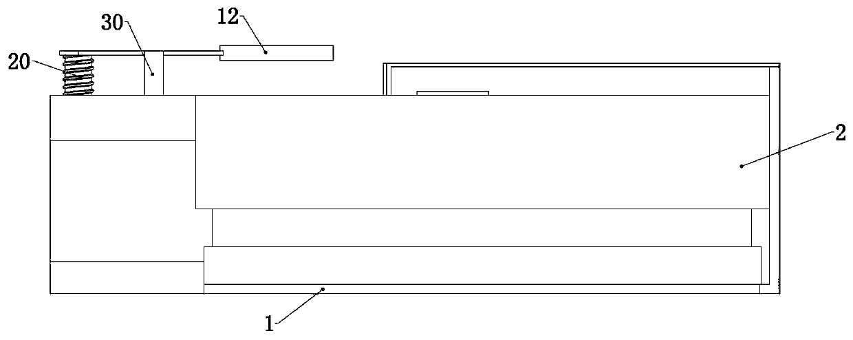
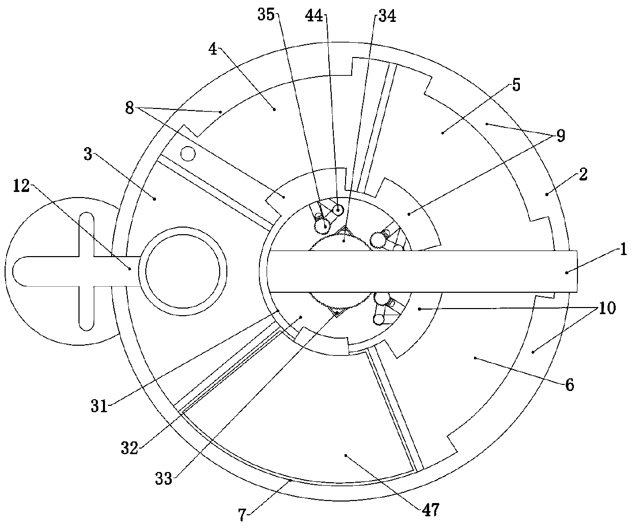
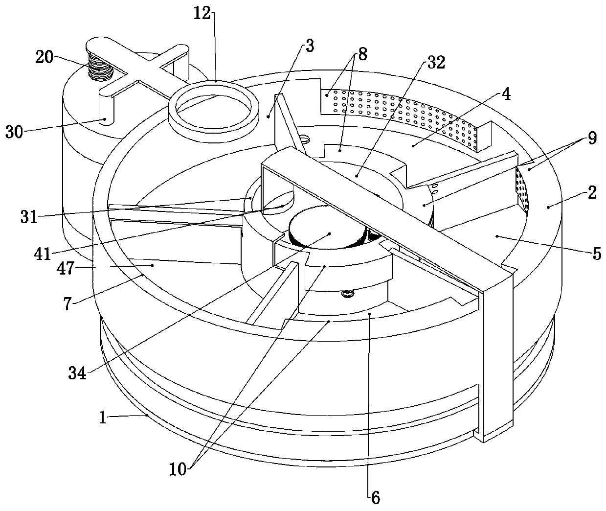
[0034]Embodiment 1, the present invention is an ultrasonic image probe cleaning device, which is characterized in that it includes a main body 1, the main body 1 can be placed on a desktop to provide a fixed basis for subsequent structures, and the main body 1 is rotatably connected to the device. The hollow topless turntable 2, the turntable 2 is evenly divided into five areas and is divided into a waiting area 3, a disinfection and cleaning area 4, a drying area 5, a sterilization area 6, and a liquid dip area 7. The disinfection and cleaning area 4 is fixedly connected with a spray device 8, the drying area 5 is fixedly connected with a dryer 9, and the sterilization area 6 is fixedly connected with a sterilization device 10. Waiting area 3 is used for daily placement of probes. It is a hollow shell without debris, and a collection box is also detachably installed inside it to collect the couplant left on the probe. The above-mentioned disinfection and cleaning area 4 is us...

Embodiment 2

[0035] Embodiment 2, on the basis of Embodiment 1, this embodiment provides a specific periodic lifting device 13, so that the probe support 12 can realize periodic cyclic lifting motion. Specifically, the periodic lifting device 13 includes and The lift drive gear 16 connected to the drive motor 14, specifically, the lift drive gear 16 is coaxially and fixedly connected to the output shaft of the drive motor 14, and the drive motor 14 works to drive the drive motor 14. The lift drive gear 16 rotates to serve as the power source of the periodic lift device 13. The lift drive gear 16 is meshed with a lift relay gear 17 rotatably connected to the main body 1. The lift relay gear 17 A lifting incomplete gear 18 is fixedly connected coaxially, and a threaded sleeve 19 rotatably connected to the main body 1 is meshed beside the lifting incomplete gear 18 . The screw 20 on the main body 1, the threaded sleeve 19 is a hollow cylinder rotatably connected to the main body 1, the inner ...

Embodiment 3

[0037] Embodiment 3, on the basis of Embodiment 1 or Embodiment 2, this embodiment provides a specific way of driving the motor 14 to drive the turntable 2 to rotate, so that the rotation of the turntable 2 is changed to intermittent rotation, and can match the periodicity of the probe holder 12. Specifically, the lower end of the drive motor 14 is connected to the power drive pulley 26 rotatably connected to the main body 1. Specifically, the power drive pulley 26 is coaxially and fixedly connected to the drive motor. 14 on the output shaft, refer to Figure 5 , Figure 7 It can be seen that the lift drive gear 16 and the power drive pulley 26 are located at the upper and lower ends of the drive motor 14, respectively. Therefore, the drive motor 14 should use a bidirectional output shaft motor. In fact, a conventional motor is used and the motor is placed in The device is at the bottom and the lifting drive gear 16 and the power driving pulley 26 are both coaxially and fixedly...


PUM


Abstract

The invention relates to an ultrasonic image probe cleaning device, which effectively solves the problems of complicated operation of manually wiping a probe, poor wiping effect and low medical treatment efficiency. The technical scheme is as follows: the device comprises a main body, wherein a hollow non-top turntable is rotationally connected to the main body; the turntable is uniformly dividedinto five areas and is divided into a waiting area, a disinfection cleaning area, a drying area, a sterilization area, a liquid dipping area; a spraying device is fixedly connected to the disinfectioncleaning area; a drying device is arranged in the drying area, a sterilizing device, a spraying device, a drying device and a sterilizing device are arranged in the sterilizing area and are all connected with a driving device; a probe bracket is connected with the main body in an up-down sliding manner, and the probe bracket is connected with a periodic lifting device, and the periodic lifting device is connected with a driving motor, and the driving motor is connected with the turntable driving gear, and the turntable driving gear is coaxially and fixedly connected with the turntable.The ultrasonic image probe cleaning device has the advantages of simple structure, simple and convenient operation, obvious cleaning effect, high automation degree, can greatly improve medical treatment efficiency, saves time and has strong practicability.

Description

technical field [0001] The invention relates to the technical field of ultrasonic imaging auxiliary equipment, in particular to an ultrasonic imaging probe cleaning device. Background technique [0002] Ultrasound diagnosis is a diagnostic method that applies ultrasound detection technology to the human body to understand the data and morphology of physiology or tissue structure by measuring, discovering diseases, and making prompts. Ultrasound diagnosis is a non-invasive, painless, convenient, and intuitive effective inspection method, especially B-ultrasound, which is widely used and has a great impact. Ultrasound used for medical diagnosis is mainly pulse reflection technology, including A-type, B-type, D-type, M-type, V-type, etc. From the perspective of development trends, ultrasound is already making progress towards three-dimensional display. In addition, penetration techniques and tissue characterization are also being studied for many sonographers. [0003] With ...

Claims


Application Information

Patent Timeline
Patent Type & Authority Applications(China)
IPC IPC(8): A61L2/18A61L2/24A61L2/26A61L2/10B08B3/02
Inventor 王铮胡玲
Owner HENAN PROVINCE HOSPITAL OF TCM THE SECOND AFFILIATED HOSPITAL OF HENAN UNIV OF TCM
Why Eureka
Try Eureka