
Magneto-rheological composite soft mold and plate forming method based on same

A magnetorheological and magnetorheological elastic technology, applied in the field of sheet metal forming, can solve the problems of different, incapable of forming and processing of sheet metal parts, and inability to realize local differential pressure distribution, so as to promote full filling and solve local differential pressure distribution , the effect of avoiding forming defects

Active Publication Date: 2019-05-14
HENAN UNIV OF SCI & TECH
View PDF13 Cites 13 Cited by
  • Summary
  • Abstract
  • Description
  • Claims
  • Application Information

AI Technical Summary

Problems solved by technology

[0008] The purpose of the present invention is to provide a magnetorheological composite soft mold, which is used to solve the problem that the existing magnetorheological elastomer soft mold cannot realize local differential pressure distribution. The sheet forming method of the soft mold is used to solve the problem that the existing magnetorheological elastomer soft mold forming method cannot form and process the sheet parts with local differences in structure
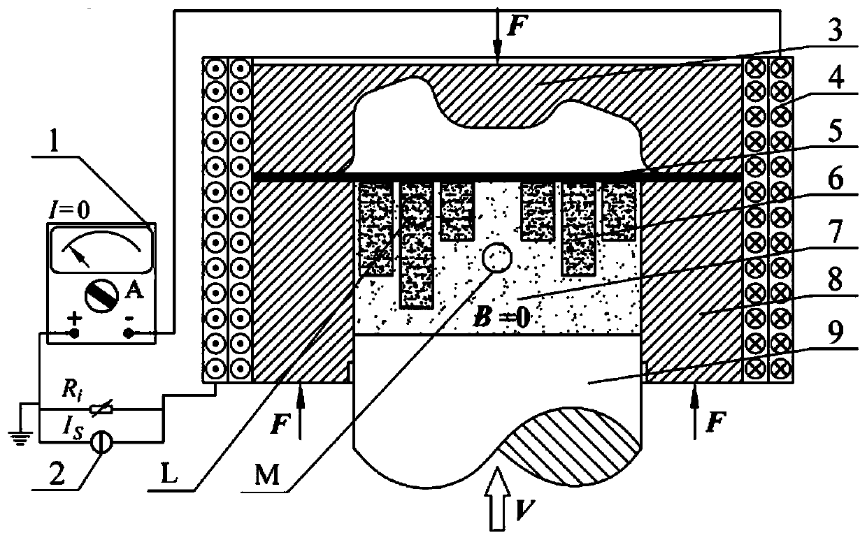
[0009] In order to solve the problem that the existing magnetorheological elastomer soft mold cannot realize local differential pressure distribution, the present invention provides a magnetorheological composite soft mold, including a soft mold base composed of type I magnetorheological elastic material, Encapsulate at least one type II magnetorheological elastic unit or at least one magnetorheological viscoplastic unit at a predetermined position in the soft mold base; the type II magnetorheological elastic unit is composed of type II magnetorheological elastic material; The magnetorheological viscoplastic unit is composed of magnetorheological viscoplastic materials; under an external magnetic field, the pressure response characteristics of the type I magnetorheological elastic materials are different from those of type II magnetorheological elastic materials and magnetorheological viscoplastic materials

Method used


Image

  • Magneto-rheological composite soft mold and plate forming method based on same
  • Magneto-rheological composite soft mold and plate forming method based on same
  • Magneto-rheological composite soft mold and plate forming method based on same

Examples


Embodiment Construction

[0032] In order to make the object, technical solution and advantages of the present invention clearer, the present invention will be further described in detail below in conjunction with the accompanying drawings and specific embodiments.

[0033] Embodiment of magnetorheological composite soft mold:

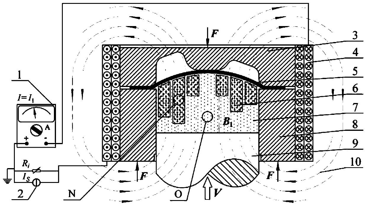
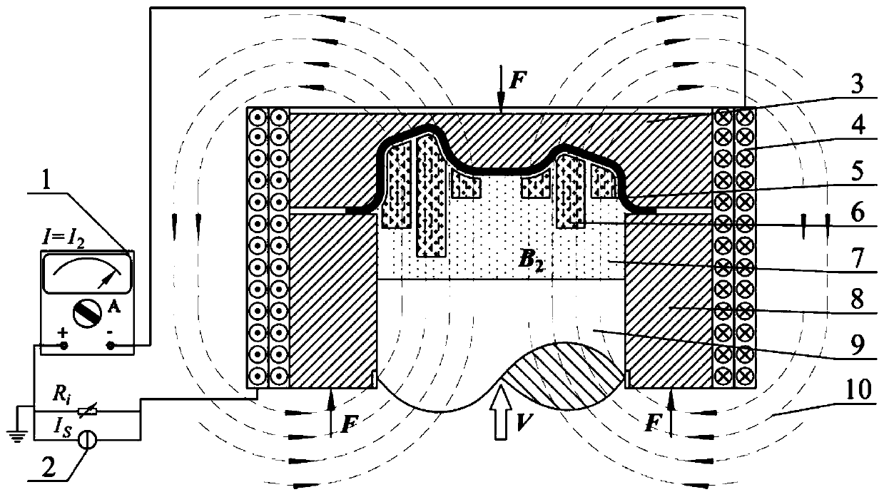
[0034] This embodiment provides a magnetorheological composite soft mold, such as figure 1 As shown, the magnetorheological composite soft mold includes a soft mold base composed of solid type I magnetorheological elastic material 7, and a semi-solid magnetorheological viscoplastic material 6 is encapsulated at a predetermined position inside the soft mold base. Six cylindrical magnetorheological viscoplastic units are formed to form a cylindrical magnetorheological elasticity-viscoplastic composite soft mold (abbreviated as a magnetorheological composite soft mold).

[0035] Wherein, the magnetorheological viscoplastic material 6 is magnetorheological fluid, magnetorheologica...


PUM

PropertyMeasurementUnit
viscosityaaaaaaaaaa
particle diameteraaaaaaaaaa
thicknessaaaaaaaaaa

Abstract

The invention relates to a magneto-rheological composite soft mold and a plate forming method based on the same. The magneto-rheological composite soft mold comprises a soft mold matrix constituted byI-type magneto-rheological elastic materials, and one or more II-type magneto-rheological elastic units or one or more magneto-rheological visco-plastic units are packaged at the predetermined position in the soft mold matrix; the II-type magneto-rheological elastic units are constituted by II-type magneto-rheological elastic materials; the magneto-rheological visco-plastic units are constitutedby magneto-rheological visco-plastic materials; and in an applied magnetic field, the pressure response characteristics of the I-type magneto-rheological elastic materials, the II-type magneto-rheological elastic materials and the magneto-rheological visco-plastic materials are different. The magneto-rheological composite soft mold is used as a plate forming force-transmitting medium, full fillingof plate local complex structural characteristics can be promoted, the forming defects are avoided, and the problem that an existing magneto-rheological elastomer soft mold cannot achieve local differential pressure distribution is effectively solved.

Description

technical field [0001] The invention relates to a magnetorheological composite soft mold and a plate forming method based on the magnetorheological composite soft mold, belonging to the technical field of plate forming. Background technique [0002] Thin-walled shell parts with complex shapes, such as aero-engine heat shields, hollow blades, special-shaped nozzles, etc., can realize special part functions, improve the lightweight level of equipment, and improve equipment performance. Due to the comprehensive consideration of assembly position, weight reduction, aerodynamics and other factors, such thin-walled shell parts with complex shapes have structural characteristics such as thin walls, non-rotation, and local curvature mutations, which increase the stress in the sheet forming process. Control difficulty. [0003] If such parts are formed by stamping in pieces and combined welding, there will be problems such as difficult positioning, thermal deformation of welding, an...

Claims


Application Information

Patent Timeline
Patent Type & Authority Applications(China)
IPC IPC(8): B21D26/021B21D26/031B21D26/14
Inventor 相楠皇涛郭俊卿宋亚虎马窦琴
Owner HENAN UNIV OF SCI & TECH
Learn More