Steel wire knitted hose cutting machine and working method thereof

A steel wire braided hose and cutting machine technology, applied in manufacturing tools, metal processing equipment, laser welding equipment, etc., can solve the problems of pollution, poor cutting surface roughness of the hose, noise and dust, etc., to improve safety performance and reduce heat. The effect of small shadow area and heat affected zone

Inactive Publication Date: 2019-05-14
NANJING LINGQUE INTELLIGENT MFG CO LTD
View PDF8 Cites 0 Cited by
  • Summary
  • Abstract
  • Description
  • Claims
  • Application Information

AI Technical Summary

Problems solved by technology

The structure of the cutting machine produced in our country is simple and the cutting efficiency is not high. Although after decades of development, the quality of the product has been improved earlier
[0003] Although traditional mechanical cutting can also cut steel wire braided hoses, due to the different materials of steel wire braided hoses, cutting will produce blade deformation, burrs and wear, and the cutting blades need to be replaced frequently. At the same time, the material utilization rate is low, and it is safe for operators. There is a greater threat, and there is also serious noise and dust pollution
[0004] Because the steel wire braided rubber hose composed of two materials is cut at the same time because the steel wire is braided on the outside of the rubber hose, the finished product cut by the cutting machine is easy to cause the steel wire at the cutting place to explode, and the roughness of the cut surface of the rubber hose is poor. Cutting speed is slower

Method used


Image

  • Steel wire knitted hose cutting machine and working method thereof
  • Steel wire knitted hose cutting machine and working method thereof
  • Steel wire knitted hose cutting machine and working method thereof

Examples


Embodiment Construction

[0040] In the following description, numerous specific details are given in order to provide a more thorough understanding of the present invention. It will be apparent, however, to one skilled in the art that embodiments of the invention may be practiced without one or more of these details. In other examples, in order to avoid confusion with the embodiments of the present invention, some technical features known in the art are not described.

[0041] In describing the present invention, it should be understood that the terms "upper", "lower", "front", "rear", "left", "right", "top", "bottom", "inner", " The orientation or positional relationship indicated by "outside", etc. is based on the orientation or positional relationship shown in the drawings, and is only for the convenience of describing the present invention and simplifying the description, rather than indicating or implying that the referred device or element must have a specific orientation, so as to Specific ori...


PUM


Abstract

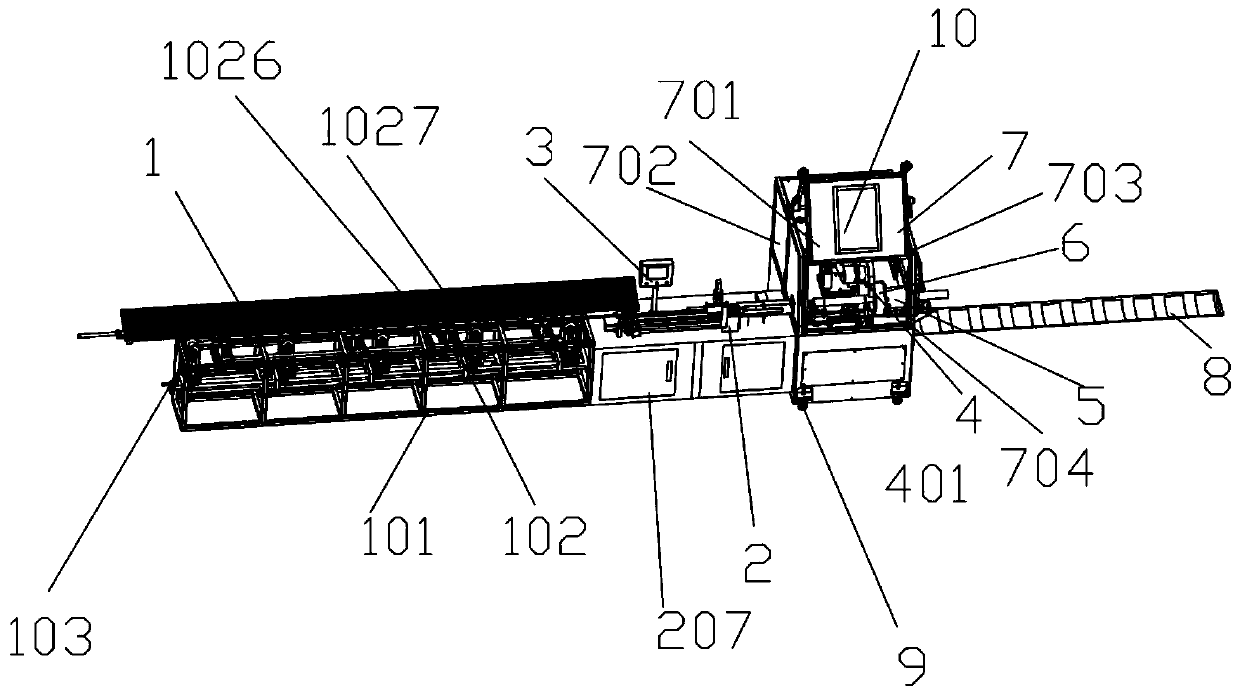
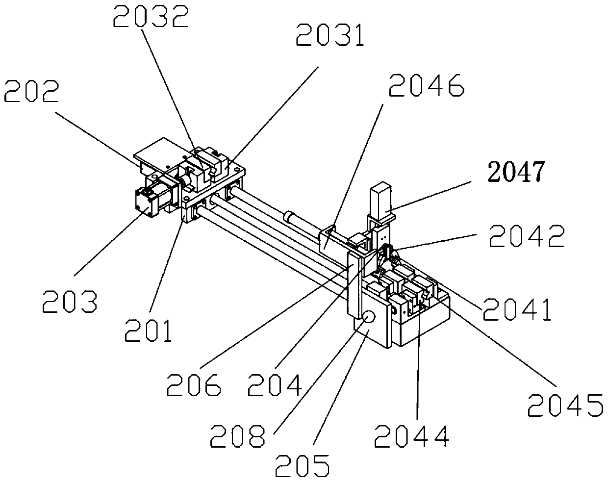
The invention discloses a steel wire knitted hose cutting machine and a working method thereof, and belongs to the field of pipeline cutting. The steel wire knitted hose cutting machine includes a feeding mechanism, a feeding clamping mechanism, a hot melting mechanism and a laser cutting device. The hot melting mechanism includes a hot melting plate, a hot melting head, a heating block, a hot-melting heat-dissipation block, a heat insulating plate, a temperature sensor and a hot melting guide pillar; the hot melting plate is arranged in a three-gripper clamping mechanism, the hot melting headis fixedly connected to the hot melting plate, the heating block is arranged on one end of the hot melting head, the hot-melting heat-dissipation block is fixedly connected to the heating block, theheat insulating plate is fixedly connected to the end, with quick heat dissipation, of the hot melting block, the temperature sensor is arranged on the heating block, and the hot melting guide pillaris arranged to penetrate through the hot melting plate; and according to the laser cutting device, the cutting speed is fast, the power demand is low, meanwhile the focal position is placed at the middle of materials, the internal stress change is induced, no traces exists on the surface, meanwhile the cutting surface is smooth, no cutting traces exists, the cutting efficiency is improved, no chemical waste gas, dust and noise pollution exists, and the harm on the environment is avoided.

Description

technical field [0001] The invention belongs to the field of intelligent cutting, in particular to a steel wire braided rubber hose cutting machine and its working method. Background technique [0002] Pipeline cutting technology has been more widely used in rubber hose, oil pipe and other industries. The structure of the cutting machine produced in our country is simple and the cutting efficiency is not high. Although after decades of development, the quality of the products has been improved earlier. [0003] Although traditional mechanical cutting can also cut steel wire braided hoses, due to the different materials of steel wire braided hoses, cutting will produce blade deformation, burrs and wear, and the cutting blades need to be replaced frequently. At the same time, the material utilization rate is low, and it is safe for operators. The threat is greater, and there is also serious noise and dust pollution. [0004] Because the steel wire braided rubber hose compose...

Claims


Application Information

Patent Timeline
Patent Type & Authority Applications(China)
IPC IPC(8): B23K26/38B23K26/402B23K26/70B29C57/00
Inventor 许珍珍
Owner NANJING LINGQUE INTELLIGENT MFG CO LTD
Why Eureka
Try Eureka