A resistor packaging machine
A packaging machine and resistor technology, applied in packaging, transportation packaging, transportation and packaging, etc., can solve problems such as difficulty in meeting production needs, low packaging quality and efficiency, and easy cracking of solder joints, etc., to achieve accurate alignment , reduce processing costs, and achieve a high degree of automation
- Summary
- Abstract
- Description
- Claims
- Application Information
AI Technical Summary
Problems solved by technology
Method used
Image
Examples
Embodiment 1
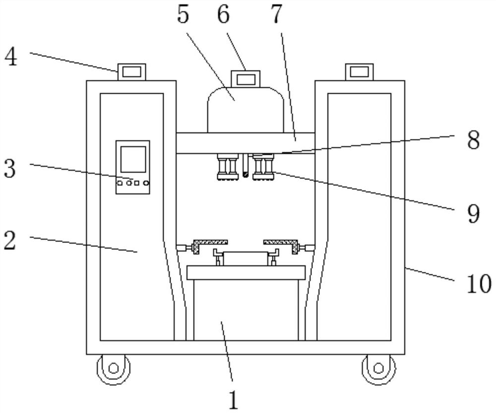
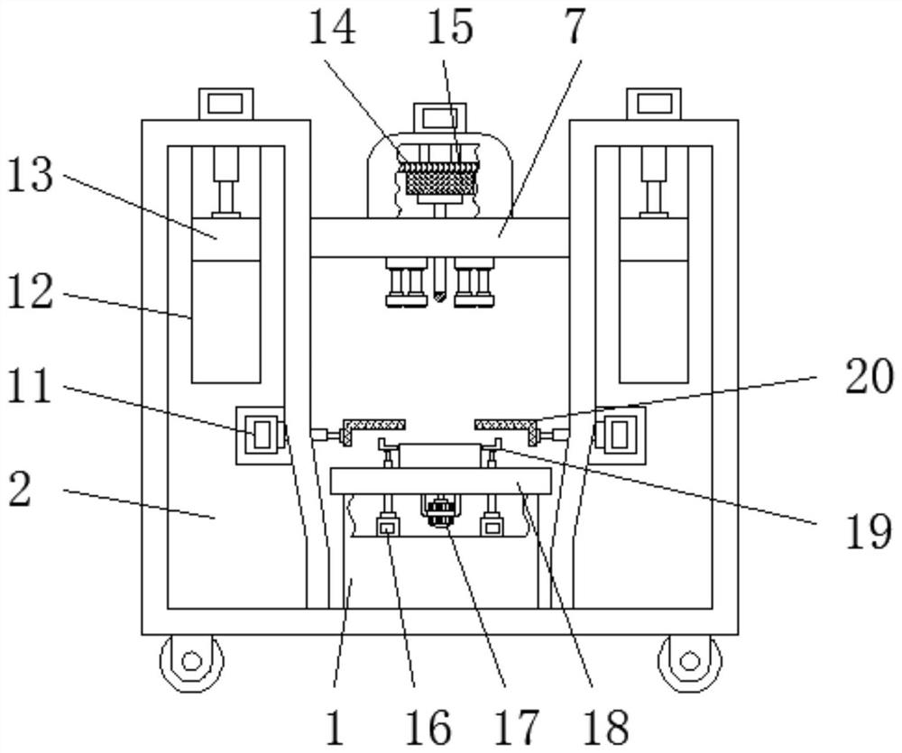
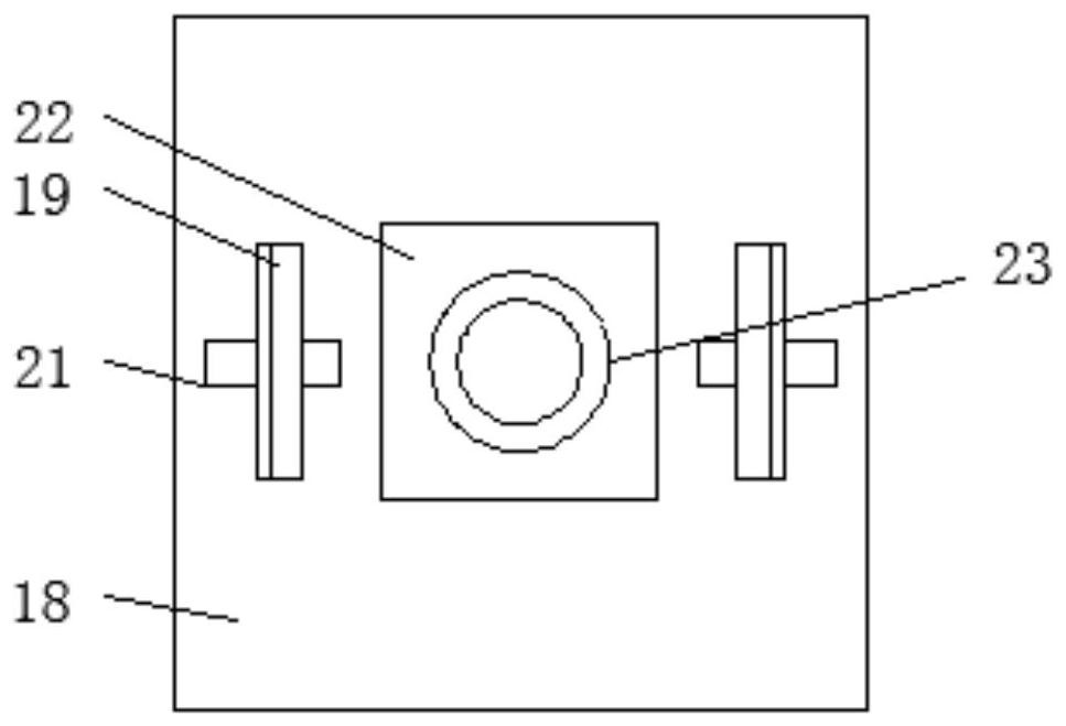
[0022] Embodiment 1, with reference to Figure 1-4 , a resistor packaging machine, including a packaging machine body 10, side cabinets 2 are arranged on both sides above the packaging machine body 10, a control panel 3 is embedded in the front surface of one of the side cabinets 2, and the packaging machine body 10 is located below the two sides The main chassis 1 is welded between the chassis 2, and the packaging platform 18 is welded above the main chassis 1. The upper surface of the packaging platform 18 is embedded with a bearing plate 23, and the upper surface of the bearing plate 23 is rotatably fitted with a placement plate 22. The setting of this structure makes The placement plate 22 is a rotatable structure, which is more convenient for all-round packaging when the resistors are packaged. The upper part of the packaging machine body 10 is located between the two side chassis 2, and the lifting main board 7 is clamped by the limit slider 13. The function of the slide...
Embodiment 2
[0024] Embodiment 2, with reference to Figure 1-4 , the main box 1 inner center is bolted with a stepper motor 17, and the output shaft of the stepper motor 17 runs through the main box 1 and the packaging platform 18 and the bottom of the placement plate 22. The rotation angle of the stepper motor 17 is 90°, when The stepper motor 17 can drive the placement plate 22 to rotate when it is in operation. The inside of the main box 1 is located at both sides of the stepper motor 17 and is symmetrically fixed with two electric cylinders D16 by bolts. Push plate 19, the upper surface of packaging table 18 is symmetrically provided with two second chute 21, the piston rod of electric cylinder D16 passes through second chute 21, there are two side push plates 19 in total, and two side push plates 19. The vertical center line of the packaging machine body 10 is symmetrical to each other. The side push plate 19 has an L-shaped structure. When the electric cylinder D16 is running, the s...
Embodiment 3
[0025] Embodiment 3, with reference to Figure 1-4 There is a first chute 12 above the inside of the side chassis 2, and the limit slider 13 is clamped in the first chute 12. The electric cylinder A4 is fixed to the top bolt of the side chassis 2, and the piston rod of the electric cylinder A4 extends to the first The chute 12 is welded to the top of the limit slider 13. When the electric cylinder A4 is running, the limit slider 13 can be pushed to slide at a constant speed in the vertical direction inside the first chute 12, thereby driving the lifting main board 7 to move at a constant speed in the vertical direction. Moving, the inside of the side cabinet 2 is located at the same horizontal line as the placement plate 22, and an electric cylinder C11 is embedded. The free end of the piston rod of the electric cylinder C11 penetrates the outer wall of the side cabinet 2 and is welded with a push plate 20. The push plate 20 is an L-shaped structure. When the electric cylinder...
PUM
 Abstract
Description
Claims
Application Information
 - R&D
- Intellectual Property
- Life Sciences
- Materials
- Tech Scout
- Unparalleled Data Quality
- Higher Quality Content
- 60% Fewer Hallucinations
Browse by: Latest US Patents, China's latest patents, Technical Efficacy Thesaurus, Application Domain, Technology Topic, Popular Technical Reports.
© 2025 PatSnap. All rights reserved.Legal|Privacy policy|Modern Slavery Act Transparency Statement|Sitemap|About US| Contact US: help@patsnap.com


