
Excavator quick replacement connector

A conversion joint and quick conversion technology, which is applied in the direction of mechanically driven excavators/dredgers, etc., can solve the problems of high cost of hydraulic joints, consume a lot of physical strength, and long operation time, so as to achieve low production costs, improve work efficiency, The effect of reducing labor intensity

Pending Publication Date: 2019-05-14
于兴辉
View PDF1 Cites 1 Cited by
  • Summary
  • Abstract
  • Description
  • Claims
  • Application Information

AI Technical Summary

Problems solved by technology

[0003] The cost of hydraulic joints is relatively high, and the movable hook is controlled by a hydraulic rod to expand and contract to realize the installation of the bucket. It also takes a few seconds and needs to be connected with the hydraulic system of the excavator, which is prone to failure
[0004] The structure of the existing mechanical quick adapter is relatively complicated, and the operation time is long and it is a waste of time
Patent No.: CN201710298205.6 discloses a quick joint for excavators. The joint needs to manually turn the adjusting bolt to make the lock block slide back and forth, and then adjust the rotation of the movable hook, and then hook the bucket tightly. Since the pitch of the bolt is limited, it is necessary to adjust the To achieve the rotation angle of the movable hook, it must first be inserted into the bucket installation shaft and then hooked to the installation shaft. It needs repeated rotation of the bolt to achieve it, and the lock block is tightened by the spring. Turning the bolt will consume a lot of physical strength and waste more time. , so that the actual operation effect is not ideal. Therefore, a new type of excavator quick adapter is very much needed to solve the above problems.

Method used


Image

  • Excavator quick replacement connector
  • Excavator quick replacement connector
  • Excavator quick replacement connector

Examples


Embodiment Construction

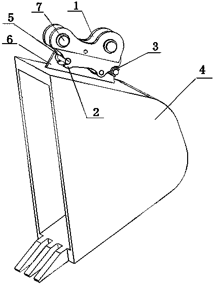
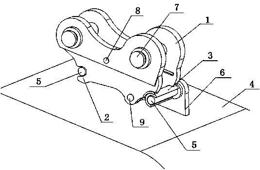
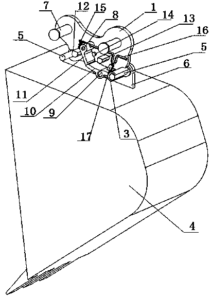
[0042] like Figure 1-19 As shown, a quick adapter for an excavator includes an adapter frame body 1, a fixed hook and a movable hook. The top of the adapter frame body 1 is provided with an arm mounting hole 21 for assembling with the arm of the excavator. The adapter frame body 1 The bottom is provided with two left and right hooks, the left hook 2 is a fixed hook, the right hook 3 is a movable hook, and the conversion adapter frame body 1 clamps the bucket installation shaft 4 of the bucket connection seat 6 through the fixed hook and the movable hook. The movable hook mentioned above is fixed by a locking device;

[0043] The adapter frame body 1 is composed of the front and rear side panels, the middle rotating shaft 8, the lower rotating shaft 9, the left connecting column 12 of the frame body, the right connecting column 13 of the frame body and the baffle plate 14, and the front and rear side panels pass through the frame body The left connecting column 12 is fixedly ...


PUM


Abstract

The invention discloses an excavator quick replacement connector, and belongs to the technical field of engineering machinery. The top of a replacement connector frame body is provided with a forearminstallation hole for assembling an excavator forearm; the bottom of the replacement connector frame body is provided with a left hook and a right hook, the left hook is a fixed hook, and the right hook is a movable hook; the replacement connector frame body clamps excavator bucket installation shafts of an excavator bucket connection seat through the fixed hook and the movable hook; the movable hook is composed of a right hook body, a swing arm and a rib plate and is fixed through a locking device; the locking device is composed of a locking plate, a connection rod arm and a swinging controldevice; the swinging control device is a manual control device or an electric control device; and the swinging control device controls swinging of the locking plate, when the locking plate is reset, the swinging control device limits the swing arm of the movable hook to be fixed, clamping is achieved, swinging of the locking plate is controlled, the swing arm can swing, and the movable hook is quickly disassembled.

Description

technical field [0001] The invention relates to an excavator quick conversion joint, which belongs to the technical field of engineering machinery. Background technique [0002] In order to expand the scope of use of the excavator, the connecting rod arm of the excavator needs to use quick connectors to realize the replacement of working accessories such as buckets, breakers and hydraulic shears. Known excavator quick couplings can be divided into hydraulic type and mechanical type; [0003] The cost of the hydraulic joint is relatively high, and the installation of the bucket by controlling the expansion and contraction of the movable hook through the hydraulic rod also takes a few seconds, and it needs to be connected with the hydraulic system of the excavator, which is prone to failure. [0004] The structure of the existing mechanical quick adapter is relatively complicated, and the operation time is long and very time-consuming. Patent No.: CN201710298205.6 discloses ...

Claims


Application Information

Patent Timeline
IPC IPC(8): E02F3/96
Inventor 于兴辉于新浩
Owner 于兴辉
Learn More