Image-based bridge structure deflection measurement method

A deflection measurement and bridge structure technology, applied in image analysis, image data processing, instruments, etc., can solve problems such as time-consuming, ineffective, and insufficient engineering structure features.

Pending Publication Date: 2019-05-14
SOUTHEAST UNIV
View PDF4 Cites 26 Cited by
  • Summary
  • Abstract
  • Description
  • Claims
  • Application Information

AI Technical Summary

Problems solved by technology

The magnification factor is the link that converts image pixel displacement into actual physical displacement. There are currently two methods for solving the magnification factor. One is to calculate a magnification factor based on the pixel length in the image with a known length near the target. is the magnification factor of the measuring point, such a known length is usually the length of a member, the thickness of a beam, if there is no known length, you can paste a target surface of known size near the target or erect a steel ruler, etc. Obviously, this method has great limitations. If it is to measure a towering bridge tower or a bridge across a river, the experimenter will place the target again, which will greatly increase the difficulty and risk of the work.
The second common method is to install a laser rangefinder on the camera system, measure the distance from the optical center of the camera to the measured point, image the model through the small hole of the camera, and calculate the magnification factor of the measured point through the design parameters of the camera and lens. On the one hand, in order to facilitate the operation and accurately find the measuring point aimed at by the laser rangefinder, the laser rangefinder needs to work with the camera system through hardware modification; It is even more difficult to capture the position of the laser aiming. Moreover, when measuring long distances, it is necessary to purchase a rangefinder with a larger range and the same accuracy, which will greatly increase the measurement cost.
Template matching technology has limitations in the application of actual structures: template matching requires that the image can only be moved in parallel, if the matching target in the original image is rotated or scaled, the algorithm is invalid, and the actual engineering structure itself is not rich enough in features, often in the accuracy can not achieve the desired effect
There have been some very useful research conclusions. Among them, the features detected by the SIFT algorithm are more accurate in space and scale, but the SIFT algorithm takes a lot of time to extract feature points due to its huge amount of feature calculation; the SURF algorithm The execution time of detecting the same rich feature points is one-third of that of SIFT. At the same time, SURF also has better rotation invariance and scale invariance.

Method used


Image

  • Image-based bridge structure deflection measurement method
  • Image-based bridge structure deflection measurement method
  • Image-based bridge structure deflection measurement method

Examples


Embodiment Construction

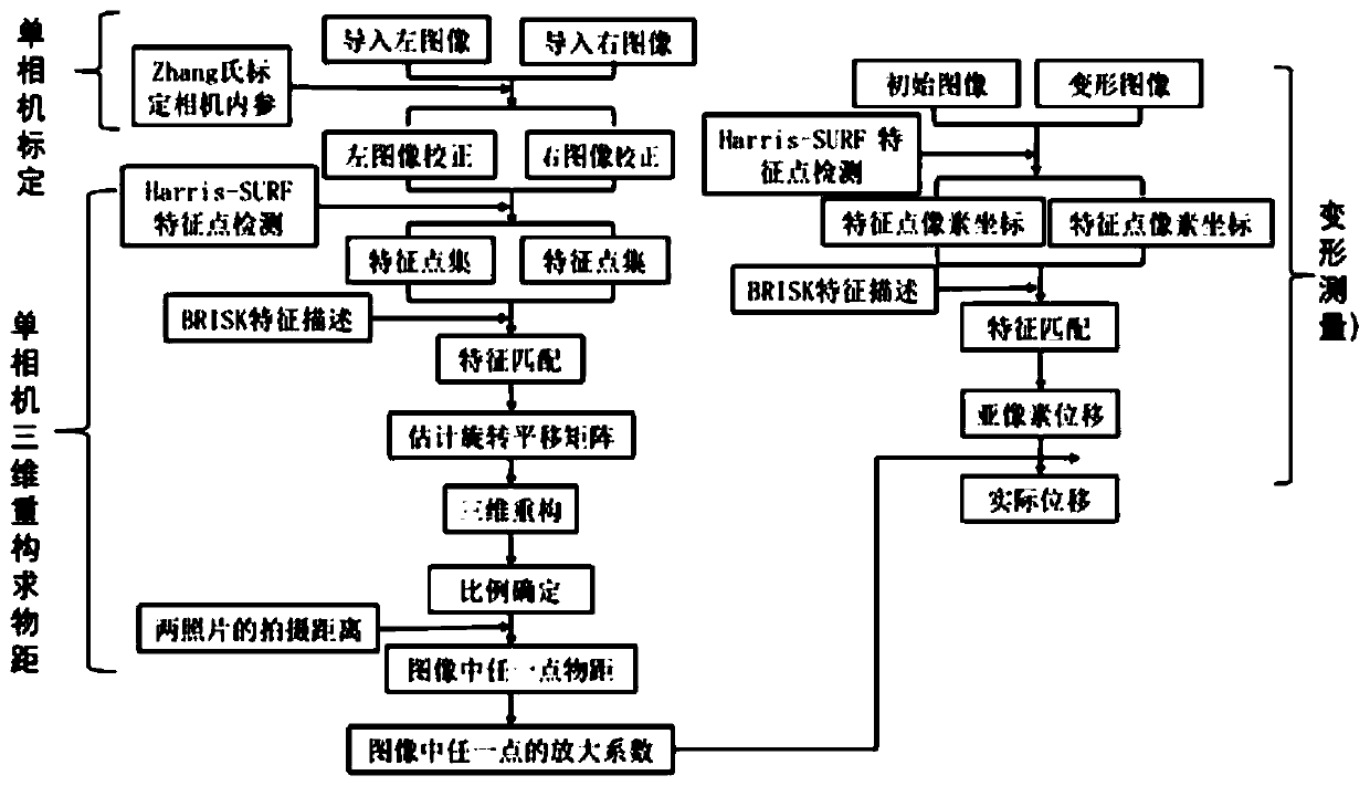
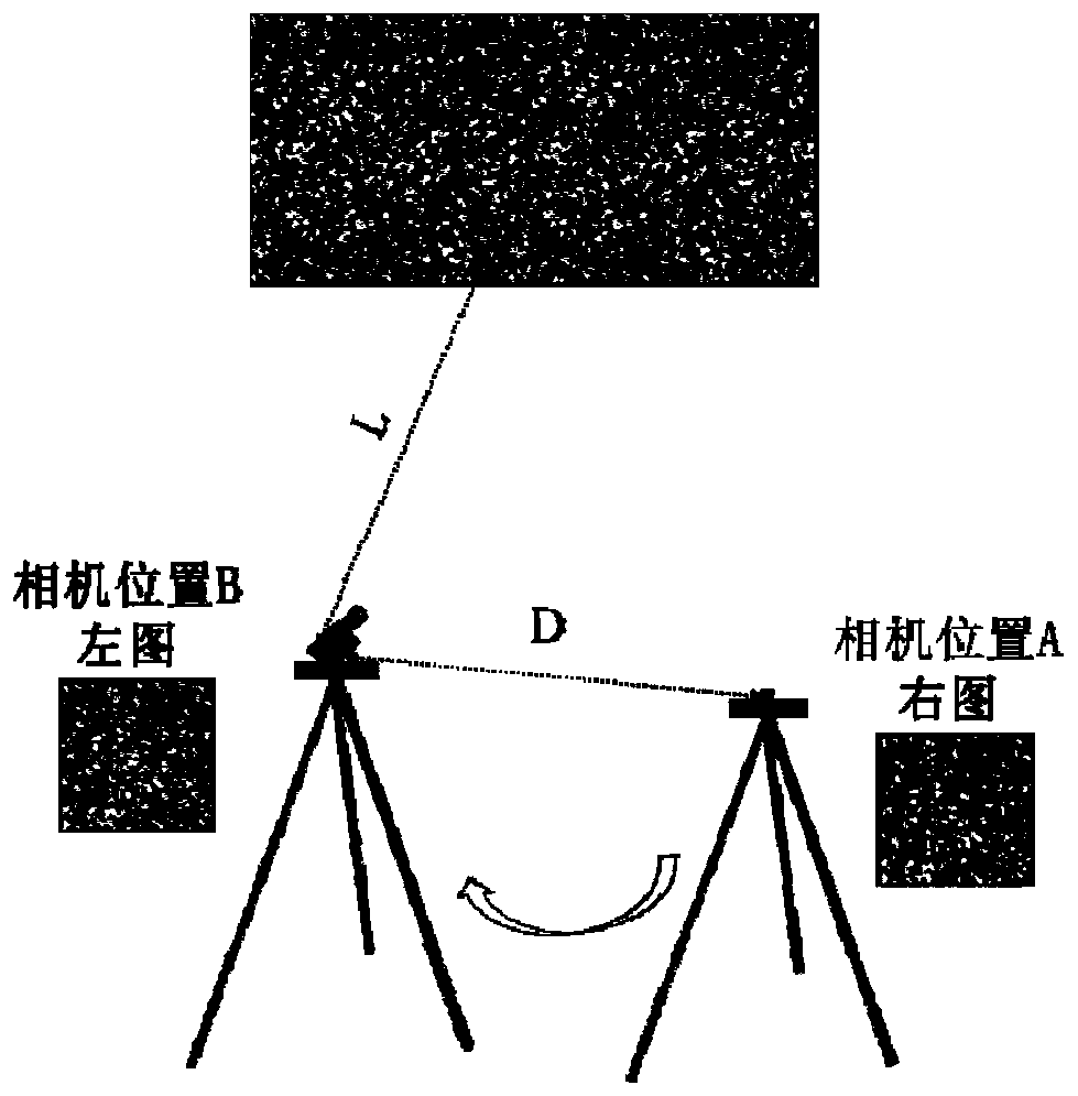
[0050] figure 1 Indicates the operation process of the present invention: after preparing the camera lens required for outdoor measurement, the internal reference calibration must be carried out first, and the present invention adopts Zhang’s calibration method; at the scene, collect left and right images, set up the camera at position A, and focus until the target structure is imaged Clear, take a picture, called the right image. The camera is set up to a new position B, and then a picture of the target structure is taken, which becomes the left image. The requirement here is that position B is as close to the same distance as position A from the target structure as possible, without refocusing. It is also important to note that the structures in the two images overlap as much as possible, such as figure 2 shown. Then, the Harris-SURF detector is used to detect the feature points of the two pictures respectively, and the BRISK descriptor is used to describe the feature p...


PUM


Abstract

The invention discloses an image-based bridge structure deflection measurement method, which comprises the following steps of: shooting a picture containing a target structure at a position A and a position B in sequence through a camera, and recording the actual distance of the camera at two positions; through a SURF-BRISK feature matching algorithm, matching the two pictures , and performing three-dimensional reconstruction on the target structure by matching with a pre-calibrated internal reference result of the camera system; obtaining three-dimensional coordinates (X, Y and Z) of any feature point on the target structure at the position B of the camera in a world coordinate system, obtaining a target amplification coefficient S of a corresponding measuring point through Z, placing thecamera at the position B for subsequent optical measurement, collecting a series of images before and after structural deformation, and obtaining the target amplification coefficient S through SURF-BRISK feature point matching algorithm, measuring two-dimensional sub-pixel displacement of the structure, and the target amplification coefficient S of a measuring point is used for converting the sub-pixel displacement into actual displacement. Structural features are directly utilized, a target surface does not need to be manually designed, and the method has the advantages of being non-contact,low in cost and high in precision.

Description

technical field [0001] The invention relates to the technical field of structural health monitoring, in particular to an image-based bridge structure deflection measurement method. Background technique [0002] Two-dimensional image measurement technology is widely used in engineering, and it is simpler and more convenient to operate than the three-dimensional measurement technology system. But there are still some key challenges hindering the widespread application and practicality of 2D imaging technology. One of the important problems is the solution of the amplification factor. The magnification factor is the link that converts image pixel displacement into actual physical displacement. There are currently two methods for solving the magnification factor. One is to calculate a magnification factor based on the pixel length in the image with a known length near the target. is the magnification factor of the measuring point, such a known length is usually the length of a...

Claims


Application Information

Patent Timeline
Patent Type & Authority Applications(China)
IPC IPC(8): G06T7/80G06T7/33
Inventor 张建于姗姗
Owner SOUTHEAST UNIV
Why Eureka
Try Eureka