Single-frequency high-gain hybrid array-element plane reflection array antenna

A planar reflection and array antenna technology, applied in the microwave field, can solve the problems of poor performance, not meeting the needs of civil and commercial use, high antenna cost, etc., and achieve the effect of low cost, easy processing and production, and optimized high gain

Inactive Publication Date: 2019-05-14
NANJING UNIV OF POSTS & TELECOMM
View PDF11 Cites 0 Cited by
  • Summary
  • Abstract
  • Description
  • Claims
  • Application Information

AI Technical Summary

Problems solved by technology

However, the traditional planar reflectarray antenna has high cost and poor performance, which does not meet the needs of civil and commercial applications.

Method used


Image

  • Single-frequency high-gain hybrid array-element plane reflection array antenna
  • Single-frequency high-gain hybrid array-element plane reflection array antenna
  • Single-frequency high-gain hybrid array-element plane reflection array antenna

Examples


Embodiment Construction

[0022] The technical solution of the present invention will be further described below in conjunction with the accompanying drawings.

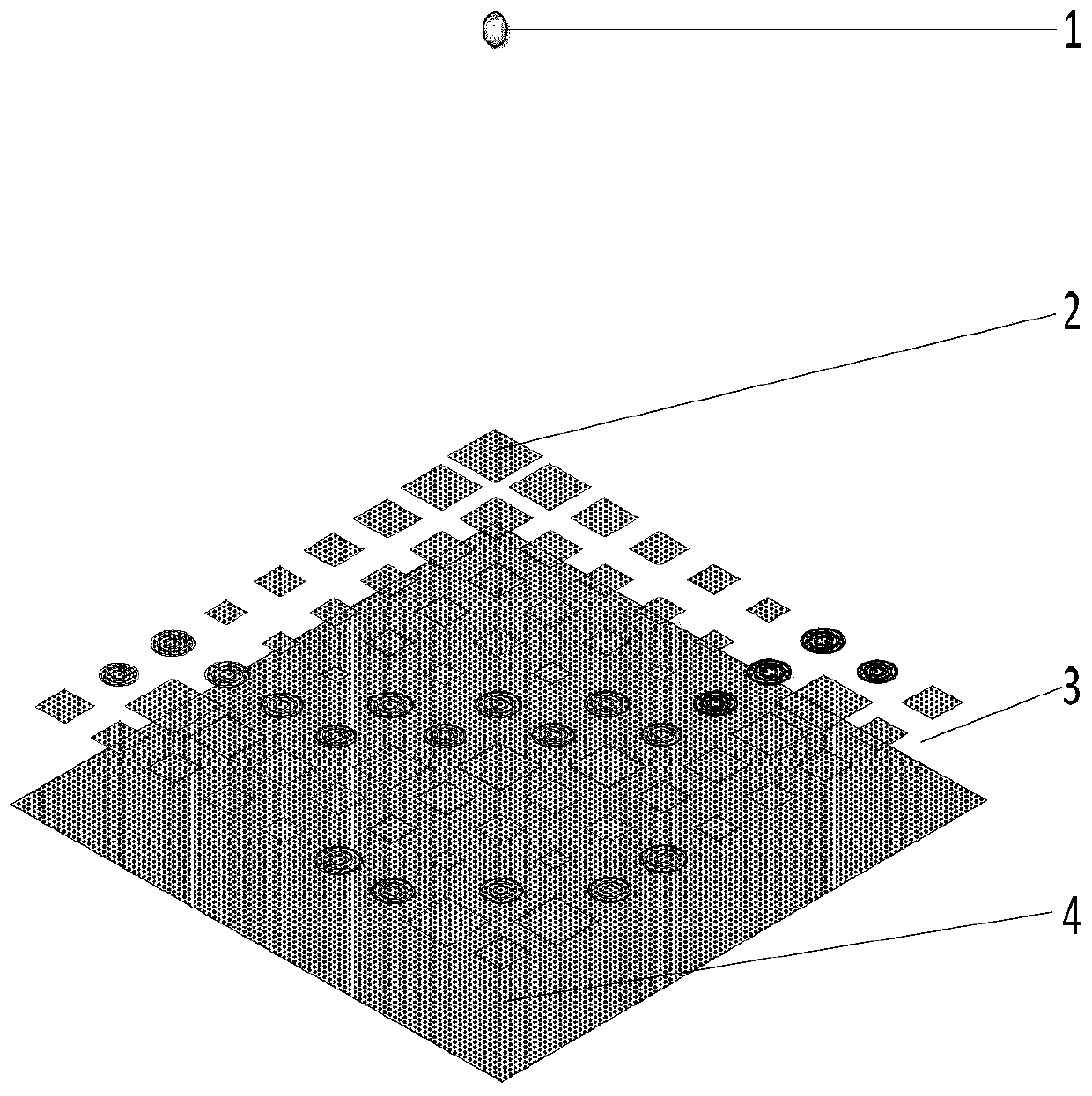
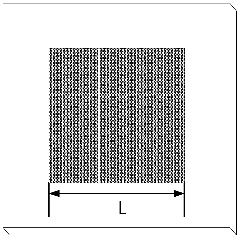
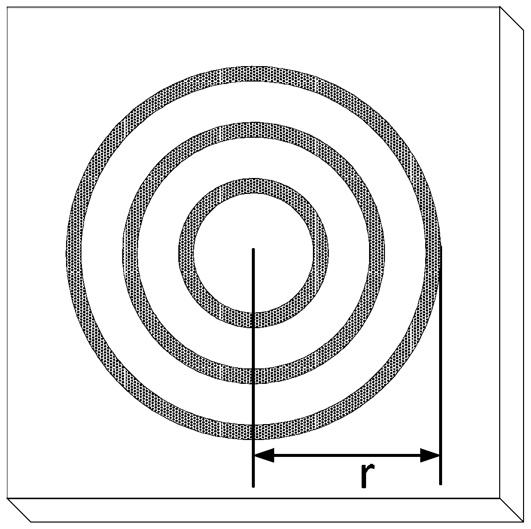
[0023] Such as Figure 1 to Figure 5 As shown, the structure of a single-frequency high-gain mixed array element planar reflectarray antenna is: the feed part 1 of the antenna adopts a horn antenna, which is placed on the mixed array element reflective surface 2, the dielectric layer 3 and the complete metal ground 4 above. The mixed array element reflective surface 2 and the complete metal ground 4 are stacked up and down and placed in parallel; the upper layer is the mixed array element reflective surface 2 composed of two different shapes of reflective units, and the reflective units are: a square patch and a three-ring patch; The lower floor is a complete metal floor 4 .

[0024] The example of the present invention uses two single-layer dielectric boards to realize the bearing of the mixed element reflection surface 2 and the complete m...


PUM


Abstract

The invention discloses a single-frequency high-gain hybrid array-element plane reflection array antenna. The antenna sequentially comprises a directional feed source, a hybrid array-element reflection surface, a medium layer and a complete metal field; the hybrid array-element reflection surface and the complete metal field are laminated up and down and are placed in parallel; and the hybrid array-element reflection surface comprises more than two different shapes of reflection units. The single-frequency high-gain hybrid array-element plane reflection array antenna is simple in structure, and by designing more than two different shapes of reflection units on the same layer and retaining and combining respective advantages of different shapes of reflection units, makes up defects generated when only one single type of array elements are adopted.

Description

technical field [0001] The invention belongs to the field of microwave technology, in particular to a single-frequency high-gain mixed element planar reflection array antenna. Background technique [0002] With the rapid development of modern satellite communication, microwave communication and aerospace technology, high-gain antennas play an extremely important role in ultra-long-distance communication. The traditional parabolic antenna is the most widely used high-gain antenna, but because of its bulky size, it does not meet the "miniaturization" requirements of today's mobile communications; the antenna array method can also greatly increase the antenna gain, but with the size of the array The expansion of the feeder network will also greatly increase the complexity of the feeder network, resulting in increased transmission loss and affecting the overall radiation efficiency of the antenna. Combining the advantages of parabolic antenna and microstrip array antenna, a new...

Claims


Application Information

Patent Timeline
IPC IPC(8): H01Q1/48H01Q13/02H01Q15/14H01Q19/10
Inventor 王翔宇黄晓东程崇虎
Owner NANJING UNIV OF POSTS & TELECOMM
Why Eureka
Try Eureka