Novel 35kV switch cabinet body structure

A switch cabinet and cabinet body technology, which is applied in the cooling/ventilation of substation/switchgear, substation/power distribution device shell, etc., can solve the problems of sparks, danger of staff touching, and failure to find in time, etc., to achieve convenience Mobile, easy to know effect

Inactive Publication Date: 2019-05-14
XINJIANG TBEA AUTOMATIC EQUIP
View PDF4 Cites 4 Cited by
  • Summary
  • Abstract
  • Description
  • Claims
  • Application Information

AI Technical Summary

Problems solved by technology

[0007] The purpose of the present invention is to provide a new type of 35kV switchgear cabinet body structure, to solve the above-mentioned background technology that the general switchgear cabinet body is made of steel plate or iron plate, easy to conduct electricity, once leakage occurs inside the cabinet body, it will make The cabinet is live, and it will be dangerous if the staff touch it without knowing it; when the general switch cabinet is hit hard or the internal temperature is too high, the electrical components inside the cabinet may generate sparks when it is powered on. It will cause greater danger and need to cut off the power, but it is usually found by people to manually cut off the power, which is more troublesome and not timely enough; there are many components in the general switchgear cabinet, and sometimes it is impossible to find the location of the corresponding components in time, so that they can be repaired Inconvenience and other problems caused by the work of personnel

Method used


Image

  • Novel 35kV switch cabinet body structure
  • Novel 35kV switch cabinet body structure
  • Novel 35kV switch cabinet body structure

Examples


Embodiment Construction

[0027] The following will clearly and completely describe the technical solutions in the embodiments of the present invention with reference to the accompanying drawings in the embodiments of the present invention. Obviously, the described embodiments are only some, not all, embodiments of the present invention. Based on the embodiments of the present invention, all other embodiments obtained by persons of ordinary skill in the art without making creative efforts belong to the protection scope of the present invention.

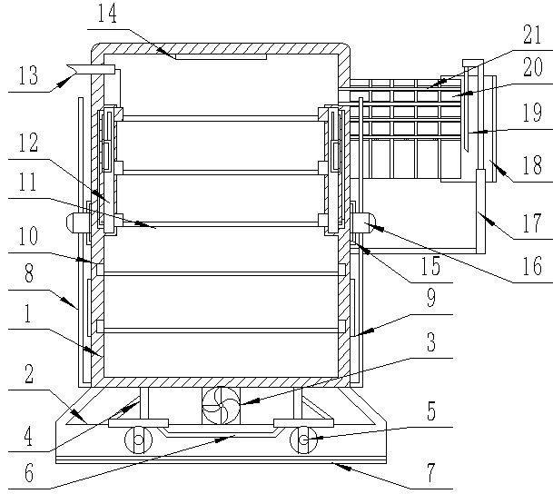
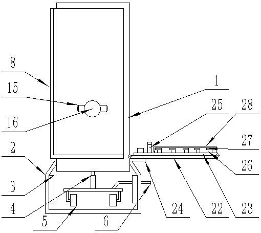
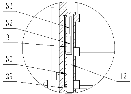
[0028] see Figure 1-5 , the present invention provides a technical solution: a new type of 35kV switchgear cabinet body structure, including a cabinet body 1, the cabinet body 1 is made of steel plates, the bottom of the cabinet body 1 is fixedly connected with a support frame 2 and the support frame 2 There is a distance between the bottom plate of the cabinet body 1 and the bottom plate of the cabinet body 1. The left and right inner walls of the cabinet bo...


PUM


Abstract

The invention discloses a novel 35kV switch cabinet body structure. The novel 35kV switch cabinet body structure comprises a cabinet body, wherein the cabinet body is made of steel plates; a supporting frame is fixedly connected to the bottom of the cabinet body, and a space exists between a bottom plate of the supporting frame and a bottom plate of the cabinet body; electric sliding rails are equidistantly and fixedly connected to the left inner wall and the right inner wall of the cabinet body from top to bottom, and the electric sliding rails are parallel left to right and exist in pairs; meanwhile, connecting circuits of the electric sliding rails are mutually connected in parallel; and supporting plates are horizontally and slidably connected between the electric sliding rails. According to the novel 35kV switch cabinet body structure, corresponding electronic control switches are determined to press through label paper, so that the electric sliding rails at corresponding positions drive the supporting plates and electrical apparatus elements placed in a supporting mode to slide out, when the cabinet body is hit hard or the temperature inside the cabinet body is too high, a gravity induction switch and a temperature induction switch enable a hydraulic rod to start and to shrink downwards, so that connected blade are enabled to slide downwards from the right end of a threading plate to cut off piercing wire end heads, so that elements inside the cabinet body are subjected to power failure, and the occurrence of accidents is avoided.

Description

technical field [0001] The invention relates to the technical field of 35kV switchgear cabinets, in particular to a novel 35kV switchgear cabinet structure. Background technique [0002] In the power distribution system, the high-voltage switchgear is an important component of the equipment. It plays the role of on-off, control or protection in the power generation, transmission, distribution, power conversion and consumption of the power system. It is mainly suitable for power plants, Substations, petrochemical, metallurgical steel rolling, light industry textiles, factories and mines, residential quarters, high-rise buildings and other places. [0003] The traditional switchgear cabinet structure has the following shortcomings: [0004] 1. Generally, the switch cabinet body is made of steel plate or iron plate, which is easy to conduct electricity. Once leakage occurs inside the cabinet body, it will make the cabinet body electrified, and the staff will be dangerous if th...

Claims


Application Information

Patent Timeline
Patent Type & Authority Applications(China)
IPC IPC(8): H02B1/30H02B1/56
Inventor 陈召敬孟永平贾耀华
Owner XINJIANG TBEA AUTOMATIC EQUIP
Why Eureka
Try Eureka