Supercharge Your Innovation With Domain-Expert AI Agents!

Convenient-to-maintain bus-bar cast-welding mould capable of beating heated quickly

A technology for convenient maintenance and casting and welding molds, which is applied in the field of molds, can solve the problems of heating or cooling, rapid uniformity, etc., and achieve the effects of convenient local maintenance and replacement, improving casting and welding quality, and reducing casting and welding time consumption

Pending Publication Date: 2019-05-17
FUJIAN JIANYANG YAHENG MACHINERY MFG
View PDF2 Cites 0 Cited by
  • Summary
  • Abstract
  • Description
  • Claims
  • Application Information

AI Technical Summary

Problems solved by technology

[0005] In the prior art, most of the molds used for casting and welding busbars are integrated molding structures. Once a molding unit is worn or damaged, the entire mold needs to be removed for maintenance or scrapped. The casting and welding mold of the structure is designed as independent split modules, but it cannot solve the problem of how to connect the modules to ensure fast and uniform heating or cooling, especially the need to ensure that the spray coolant does not splash into the lead liquid of the forming unit

Method used


Image

  • Convenient-to-maintain bus-bar cast-welding mould capable of beating heated quickly
  • Convenient-to-maintain bus-bar cast-welding mould capable of beating heated quickly
  • Convenient-to-maintain bus-bar cast-welding mould capable of beating heated quickly

Examples


Embodiment 1

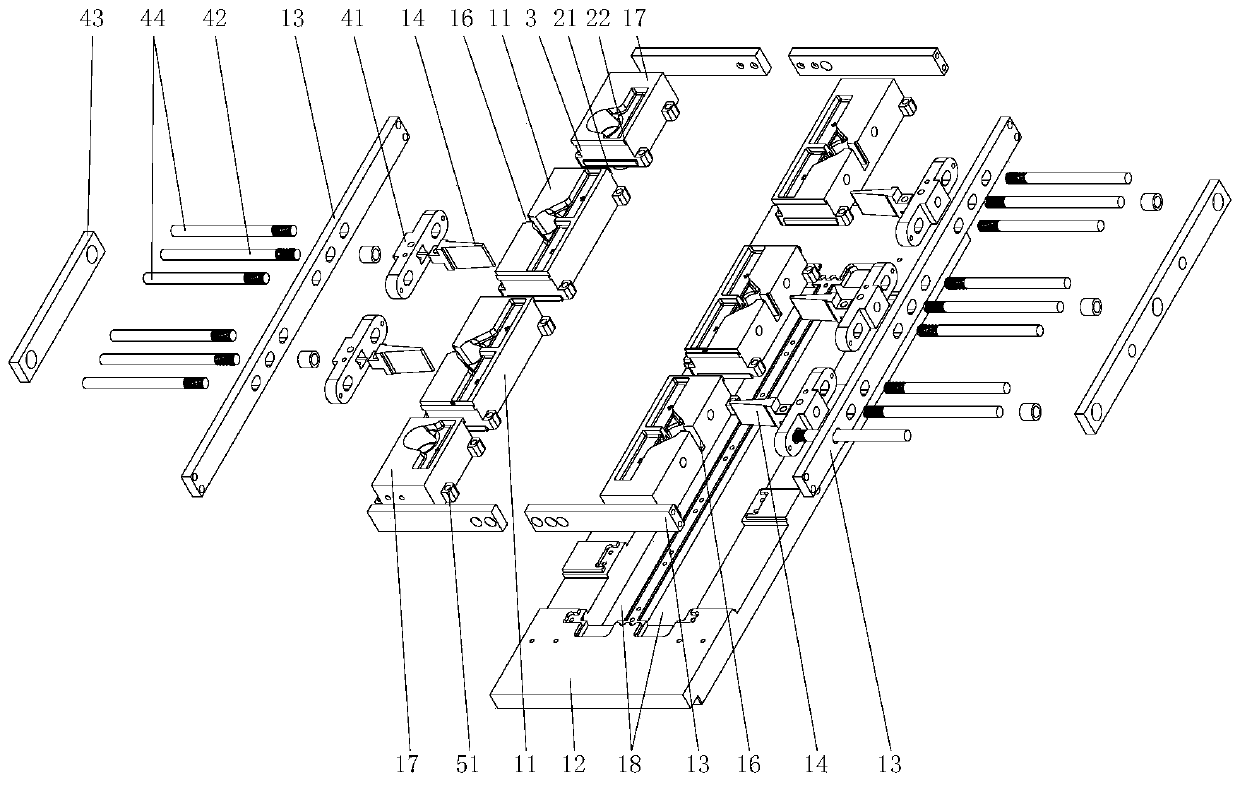
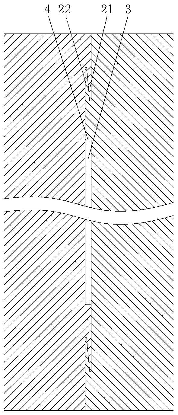
[0036] Such as image 3 As shown, the left hook 21 and the right hook 22 are set at the same width as the molding unit 11, and the openings of the left hook 21 and the right hook 22 are oppositely facing and correspondingly protruding from one end surface of two adjacent molding units 11. The left hook 21 and the right hook 22 are hooked correspondingly, so as to tightly connect the end faces of two adjacent forming units 11 to form a waterproof surface 4, and between the left hook 21, the right hook 22 and the adjacent two forming units 11 The gap channel 3 is formed by enclosing one end surface.

[0037] The left hook 21 and the right hook 22 are two pairs, and the two pairs of the left hook 21 and the right hook 22 respectively protrude from the upper and lower parts of one end surface of two adjacent molding units 11, and the left hook 21 and the right hook 22. The opening faces the opposite direction, and the two pairs of left hooks 21 and right hooks 22 are hooked corre...

Embodiment 2

[0039] Such as Figure 4 As shown, the hooking structure 2 also includes a connecting plate 23 set at the same width as the forming unit 11, and the left hook 21 and the right hook 22 are opened on the top of one end of two adjacent forming units 11 with their openings facing upwards. The lower surface of the connecting plate 23 is respectively provided with two connecting hooks 24 corresponding to the left hook 21 and the right hook 22, and the connecting plate 23 is embedded and connected between the left hook 21 and the right hook 22 by the two connecting hooks 24, so as to The upper parts of one ends of two adjacent molding units 11 are tightly connected to form a waterproof surface 4 , and the gap channel 3 is formed by enclosing the connection plate 23 and one end surface of two adjacent molding units 11 .

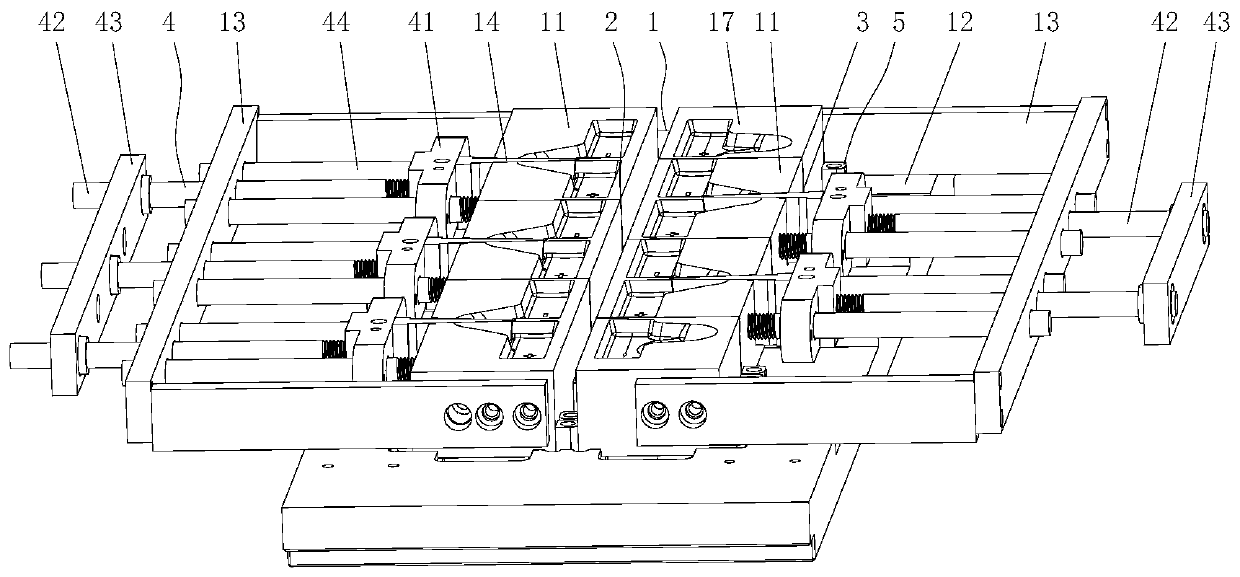
[0040] The present invention adopts the above technical scheme to separate and modularize the molding unit 11, the separator 14 and the push-pull structure 4 of the ...


PUM


Abstract

The invention relates to a convenient-to-maintain bus-bar cast-welding mould capable of being heated quickly. The convenient-to-maintain bus-bar cast-welding mould capable of being heated quickly comprises a mould body, wherein the mould body comprises a plurality of forming units which are arranged on the surface for casting a bus-bar; each forming unit consists of a positive electrode concave path, a negative electrode concave path and a gap bridge concave path for enabling the positive electrode concave path to communicate with the negative electrode concave path; the positive electrode concave paths and the negative electrode concave paths of adjacent forming units are mutually staggered; the forming units are mutually independent; ends, close to each other, of adjacent two forming units are connected through a hook joint structure which comprises a left hook and a right hook, wherein the left hook and the right hook are correspondingly arranged at ends of adjacent two forming units, the left hook and the right hook are correspondingly hooked for tightly connecting adjacent two forming units into an integer so as to define a gap channel; and the forming units can be detachablymounted on the surface of the mould body through fixing structures. The convenient-to-maintain bus-bar cast-welding mould capable of being heated quickly is simple in structure, is convenient in maintenance, is high in heating or cooling speed, and can effectively improve cast-welding quality.

Description

technical field [0001] The invention relates to the technical field of moulds, in particular to a busbar casting and welding mold which is convenient for maintenance and quick in heating. Background technique [0002] Cast welding is a crucial process in the assembly process of lead-acid batteries, which can weld multiple battery cells to form a complete battery group. The formation of the battery bus bar requires the battery cells to be fixed in the fixture first, and then the bus bar is formed on the tabs of the battery cells using a casting and welding mold, and then the positive bus bar and the negative bus bar between adjacent battery cells are connected. The busbars are soldered. Generally, an automatic busbar casting and welding machine is used to realize automatic casting and welding. The casting and welding machine includes a casting and welding mold. The surface of the casting and welding mold is provided with a casting groove. Spray the casting and welding mold ...

Claims


Application Information

Patent Timeline
IPC IPC(8): B22D19/04
CPCY02E60/10
Inventor 陈隐嵩游立强陈国刚张小瑞叶宁张磊王军人丁伟蓝继伟周友盛张振伟
Owner FUJIAN JIANYANG YAHENG MACHINERY MFG
Features
  • R&D
  • Intellectual Property
  • Life Sciences
  • Materials
  • Tech Scout
  • Unparalleled Data Quality
  • Higher Quality Content
  • 60% Fewer Hallucinations
Learn More