A welding method for dissimilar butt joints of q500qe and q690qe ultra-low carbon bainitic steel
A carbon bainitic steel and butt joint technology, applied in the field of steel bridge manufacturing, can solve problems such as difficulty, and achieve the effects of easy operation, improved low temperature impact toughness, and improved strength
- Summary
- Abstract
- Description
- Claims
- Application Information
AI Technical Summary
Problems solved by technology
Method used
Image
Examples
example 1
[0053] Base material test plate test plate: 32mmx200mmx800mm, the material is Q690qE, 44mmx 200mmx800mm material is Q500qE, different strength materials are not equal in thickness and flat; when welding, follow the steps below:
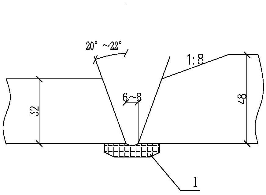
[0054] (1) Thickness reduction processing is carried out at the joint of the thick steel plates of the two unequal thickness steel plates of Q500qE and Q690qE respectively. The slope ratio of the sides is 1:8;
[0055] (2) Process a V-shaped groove at the joint of two steel plates, the groove angle is 20°-22°, the assembly gap is 6-8mm, and a ceramic liner 1 is placed on one side of the assembly gap; figure 1 shown.
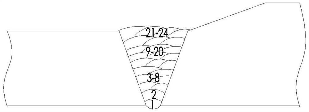
[0056] (3) Before welding, use electromagnetic induction heating equipment to preheat the steel plate. The preheating temperature of the steel plate is 75-85°C, and then use mixed gas shielded welding to weld the inner bottom of the groove. Then use solid welding wire to fill and weld layer by layer and fill the groove; clean the layer...
example 2
[0076] The base material test plate is used: 32mmx200mmx800mm, the material is Q690qE, and the material is 44mmx 200mmx800mm, the material is Q500qE, and the materials of different strengths are not equal in thickness.
[0077] (1) Thickness reduction processing is carried out at the joint of the thick steel plates of the two unequal thickness steel plates of Q500qE and Q690qE respectively. The slope ratio of the sides is 1:10;
[0078] (2) Process a V-shaped groove at the joint of two steel plates, the groove angle is 20°-22°, the assembly gap is 6mm, and a ceramic liner 1 is placed on one side of the assembly gap; figure 1 shown;
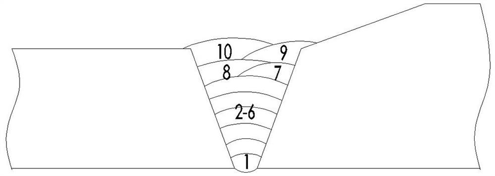
[0079] (3) Before welding, use electromagnetic induction heating equipment to preheat the steel plate. The preheating temperature of the steel plate is 75-85°C, and then use mixed gas shielded welding to weld the inner bottom of the groove. The solid welding wire is filled and welded layer by layer and the groove is filled; the interlayer cleani...
Embodiment 3
[0099] (1) Thickness reduction processing is carried out at the joint of the thick steel plates of the two unequal thickness steel plates of Q500qE and Q690qE respectively. The slope ratio of the sides is 1:9;
[0100] (2) Process a V-shaped groove at the joint of the two steel plates, the groove angle is 20°-22°, the assembly gap is 8mm, and a ceramic liner is placed on one side of the assembly gap;
[0101] (3) Before welding, use electromagnetic induction heating equipment to preheat the steel plate. The preheating temperature of the steel plate is 75-85°C, and then use mixed gas shielded welding to weld the inner bottom of the groove. The solid welding wire is filled and welded layer by layer and the groove is filled; the interlayer cleaning is carried out during the welding process, and the interlayer temperature of the weld bead is 140-160°C; when welding, vertical welding is adopted, and the welding current for backing, filling and covering is 130 —140A, welding voltag...
PUM
| Property | Measurement | Unit |
|---|---|---|
| tensile strength | aaaaa | aaaaa |
| tensile strength | aaaaa | aaaaa |
| yield strength | aaaaa | aaaaa |
Abstract
Description
Claims
Application Information
 - R&D
- Intellectual Property
- Life Sciences
- Materials
- Tech Scout
- Unparalleled Data Quality
- Higher Quality Content
- 60% Fewer Hallucinations
Browse by: Latest US Patents, China's latest patents, Technical Efficacy Thesaurus, Application Domain, Technology Topic, Popular Technical Reports.
© 2025 PatSnap. All rights reserved.Legal|Privacy policy|Modern Slavery Act Transparency Statement|Sitemap|About US| Contact US: help@patsnap.com


