Infrared main lamp light reflection module device and establishment method

A reflection and module technology, applied in lighting devices, fixed lighting devices, components of lighting devices, etc., can solve the problem of whether the reflector is separated or integrated. Service life and other issues, to improve work efficiency and accuracy, improve heat dissipation, and facilitate heat dissipation

Active Publication Date: 2019-05-17
CHINA HEFEI TAIHE OPTOELECTRONICS TECH
View PDF13 Cites 4 Cited by
  • Summary
  • Abstract
  • Description
  • Claims
  • Application Information

AI Technical Summary

Problems solved by technology

[0004] Chinese invention patent CN201710890993 discloses a light source concentrating device for color sorting machines, which uses arc-shaped reflective structures separated on both sides to gather infrared light sources. The arrangement of halogen lamps is closely spaced at equal intervals, which can effectively illuminate the background area. However, due to the large number of halogen lamps used, the heating phenomenon is more serious, which not only affects the service life of the lamp beads, but also increases the power consumption of the whole machine
Chinese invention patent CN201710890985 discloses a near-infrared multi-spectral sorting device, which uses halogen lamp beads as the light source for plastic sorting. The patent mentions that the use of a reflector can gather infrared light, but does not introduce the arrangement of the lamp beads. Whether the reflector is separate or integrated is not further explained
The existing infrared main lamp generally uses densely packed halogen lamp beads and a whole reflector as the infrared light source, but the irradiation effect of the light source is not good, and the service life of the halogen lamp is also short

Method used


Image

  • Infrared main lamp light reflection module device and establishment method
  • Infrared main lamp light reflection module device and establishment method
  • Infrared main lamp light reflection module device and establishment method

Examples


Embodiment Construction

[0039] The technical solutions in the embodiments of the present invention will be clearly and completely described below in conjunction with the embodiments of the present invention. Apparently, the described embodiments are only some of the embodiments of the present invention, not all of them. Based on the embodiments of the present invention, all other embodiments obtained by persons of ordinary skill in the art without creative efforts fall within the protection scope of the present invention.

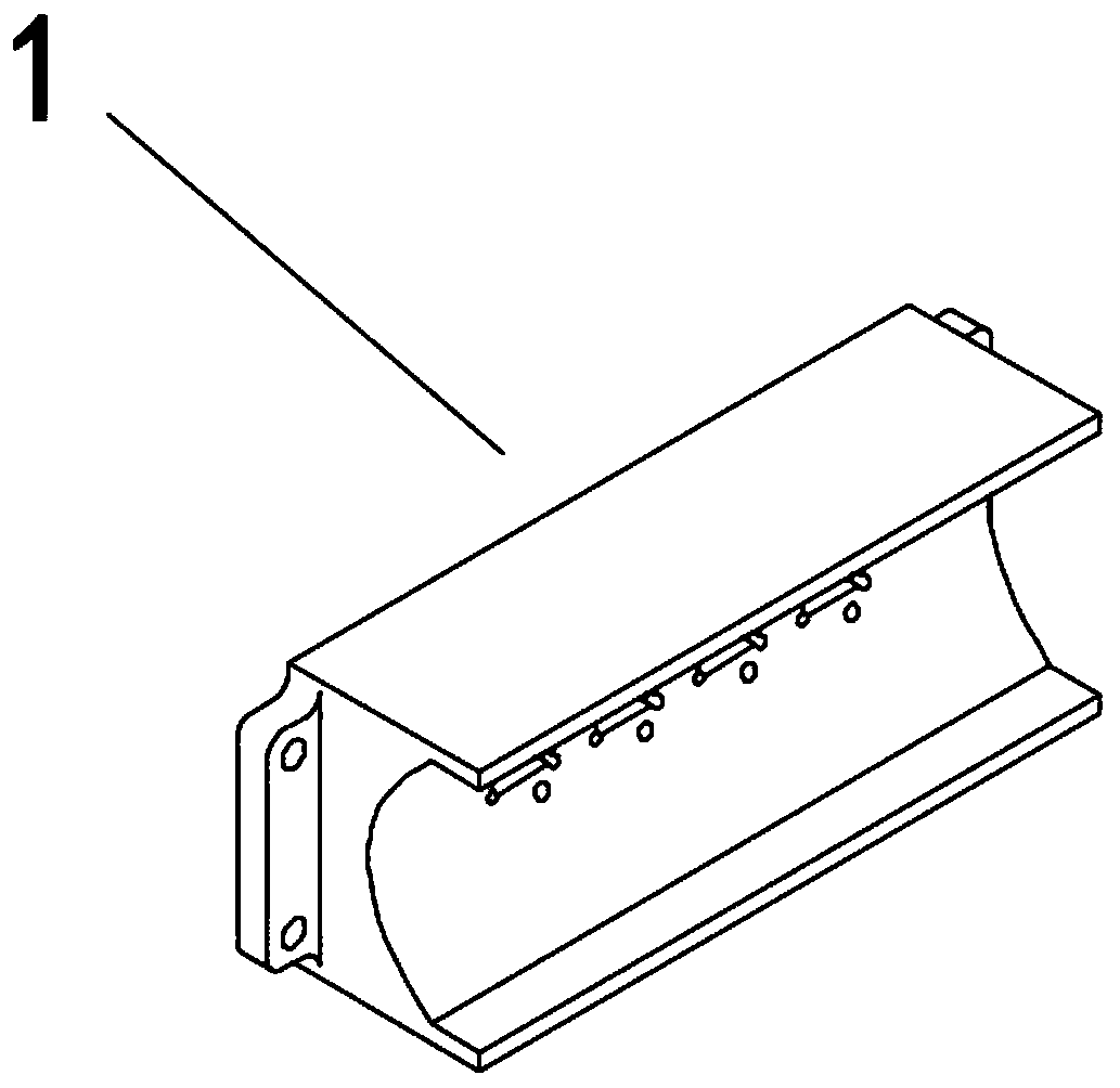
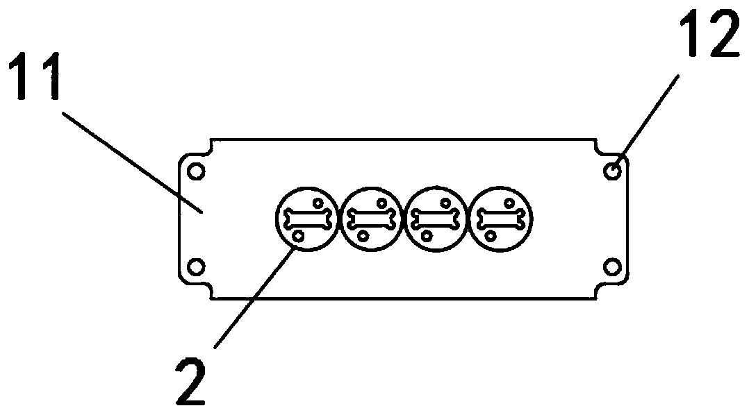
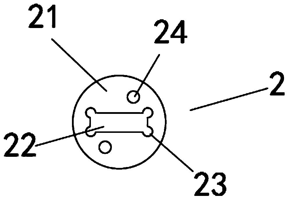
[0040] see Figure 1-9 As shown, the present invention is a reflective module device for an infrared main lamp, comprising a reflective module base mechanism 1, a halogen lamp fixing mechanism 2, a light concentrating mechanism 3, a radiator 4, a reflective module base fixing mechanism 5, and a converging module base mechanism 5. Light mechanism 3, radiator 4, halogen lamp fixing mechanism 2, reflective module base mechanism 1, and reflective module base fixing mechanism 5 are arr...


PUM


Abstract

The invention discloses an infrared main lamp light reflection module device and an establishment method. The infrared main lamp light reflection module device comprises a light reflection module basemechanism, halogen lamp fixing mechanisms, a light focusing mechanism, a heat radiator and a light reflection module base fixing mechanism, wherein four halogen lamp fixing mechanisms are mounted inthe central position of the arc-shaped surface of the light reflection module base mechanism; the light focusing mechanism is mounted above the halogen lamp fixing mechanisms; the light focusing mechanism is fixedly connected with the halogen lamp fixing mechanisms; the heat radiator is mounted in the central position inside the light focusing mechanism; and the light reflection module base fixingmechanism is mounted below the light reflection module base mechanism. By adopting the mode that light reflection modules and halogen lamps arranged at intervals, the use number of the halogen lampscan be reduced, and the use length of a light reflection cover can be reduced; in addition, because of the small amount of the halogen lamps at relatively large intervals, heat radiation can be facilitated; and due to the heat radiator mounted in the light focusing mechanism, the heat radiation effect can be further improved, and thus the service life of a halogen lamp bead can be prolonged.

Description

technical field [0001] The invention relates to a light source concentrating device of a color sorter, in particular to a reflective module device and a construction method of an infrared main lamp. Background technique [0002] With the extensive application of color sorters in the grain and oil industry, China's color sorter industry is becoming more and more mature, with more and more varieties and specifications, from the initial visible light band sorting to the current infrared band sorting, and then to the X-ray band. For sorting and ultraviolet band sorting, different bands need to have their corresponding light sources. [0003] Traditional sorting machines generally focus on color sorting of materials. The light source used is generally LED light source. This light source has the characteristics of low cost, high brightness, and long life. When the materials to be sorted are to be rejected When the color difference from good materials is small, or when it is diffi...

Claims


Application Information

Patent Timeline
IPC IPC(8): F21S8/00F21V7/04F21V5/04F21V17/16F21V19/00F21V29/503B07C5/342
Inventor 桑浩颜天信唐麟汪洪波
Owner CHINA HEFEI TAIHE OPTOELECTRONICS TECH
Why Eureka
Try Eureka