
High-coverage intranet honeypot system

A high-coverage, honeypot technology, applied in the field of network security, can solve problems affecting the allocation of business system IP addresses and occupying IP addresses, so as to increase the probability of being attacked, reduce system costs, and avoid allocation and change.

Inactive Publication Date: 2019-05-17
中国人民解放军32082部队
View PDF7 Cites 38 Cited by
  • Summary
  • Abstract
  • Description
  • Claims
  • Application Information

AI Technical Summary

Problems solved by technology

However, this method will occupy a large number of IP addresses for a long time and affect the allocation of IP addresses in the business system

Method used


Image

  • High-coverage intranet honeypot system
  • High-coverage intranet honeypot system
  • High-coverage intranet honeypot system

Examples


Embodiment 1

[0022] The following combination figure 1 and figure 2 Embodiment 1 of the present application will be described.

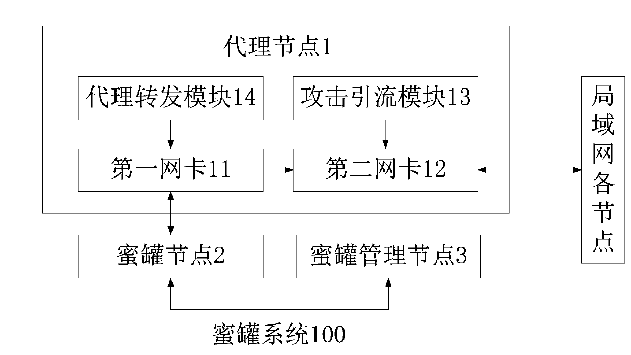
[0023] Such as figure 1 As shown, the present embodiment provides a high-coverage intranet honeypot system. The honeypot system is suitable for local area networks. The honeypot system includes: an agent node 1 and at least one honeypot node 2; the agent node 1 includes an attack drainage module 13, The first network card 11, the second network card 12 and the agent forwarding module 14, the attack diversion module 13 is used to cheat by ARP, and guide the LAN access request whose destination address is an idle IP address in the network segment where the LAN is located to the agent node 1, the first network card The IP address of 11 is in the same network segment as the honeypot IP address, the first network card 11 is used to communicate with the honeypot node 2, the IP address of the second network card 12 is in the same network segment as the IP address of ...

Embodiment 2

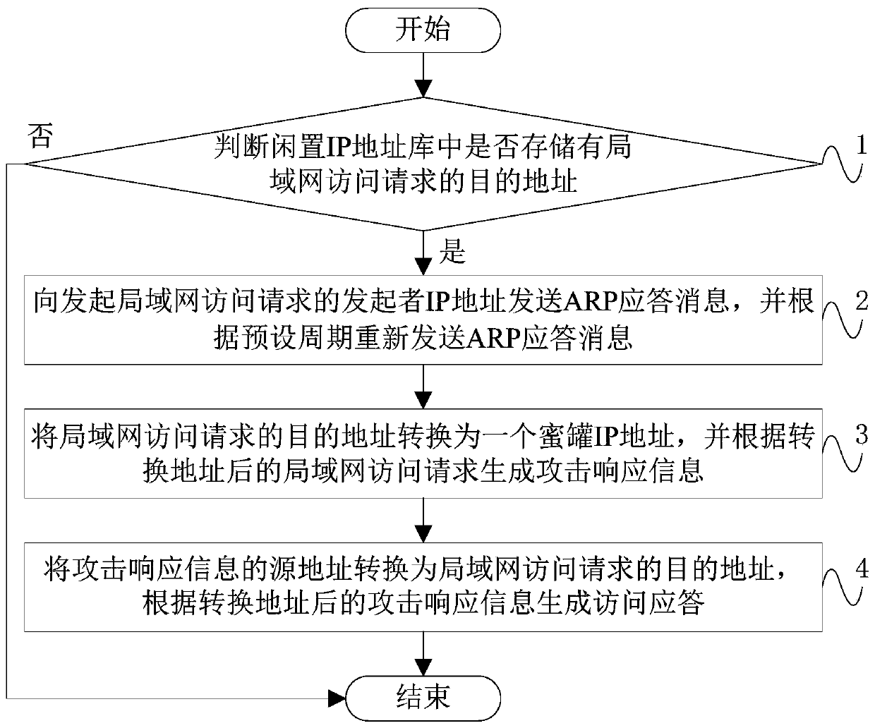
[0042] Such as image 3 As shown, the present embodiment provides a control method of a high-coverage intranet honeypot system, the control method comprising: Step 1, judging whether the destination address of the LAN access request is stored in the idle IP address library, and if so, performing the steps 2;

[0043] Step 2, sending an ARP response message to the initiator IP address of the LAN access request, and resending the ARP response message according to a preset period;

[0044] Specifically, by means of Scapy, an ARP response message is sent to the LAN IP address that initiates the access request through the second network card, and the source IP of the response message is set to the idle IP address of the ARP request, and the source mac address is set to the proxy node second network card 12 mac address to direct the connection to the proxy node. To prevent the ARP cache update from interrupting the connection, the ARP reply message is resent at a certain interval,...


PUM


Abstract

The invention discloses a high-coverage intranet honeypot system. The honeypot system comprises an agent node comprising an attack drainage module; a first network card, a second network card and a proxy forwarding module, the attack drainage module is used for passing ARP spoofing; guiding a local area network access request of which a destination address is an idle IP address in a network segment where the local area network is located to the agent node, the IP address of the first network card and the IP address of the honeypot are in the same network segment; the first network card is usedfor communicating with a honeypot node; the IP address of the second network card and the IP address of the protected device in the local area network are in the same network segment. The second network card is used for communicating with equipment in the local area network, and the agent forwarding module is used for sending the local area network access request guided to the agent node to the honeypot node and sending attack response information returned by the honeypot node to an initiator IP address of the local area network access request. Through the technical scheme provided by the invention, the IP address coverage rate of the honeypot in the honeypot system is improved while the IP address occupation of the honeypot is reduced.

Description

technical field [0001] This application relates to the technical field of network security, in particular, to a high-coverage intranet honeypot system. Background technique [0002] In order to deal with attacks from the Internet, traditional network defense technologies set up firewalls, intrusion detection systems and other devices at the network border to prevent attacks from reaching the intranet. However, attackers can still infect and control a certain host in the intranet through means such as phishing emails, and then launch other attacks on the intranet. [0003] A honeypot is a false resource that can induce attackers to attack it, and record and analyze the attack behavior. Deploying honeypots on the internal network can effectively make up for the defects of border defense equipment, send early warning information to security personnel in a timely manner, and guide reinforcement measures. In order to protect the security of the intranet to the greatest extent, ...

Claims


Application Information

Patent Timeline
IPC IPC(8): H04L29/06H04L29/12
Inventor 朱晖赵新杰郭世泽俞赛赛赵瑞昌李文胡卿石磊李剑王艺迪周子维周昆民
Owner 中国人民解放军32082部队
Learn More