On-ring artificial mechanical valve for mitral valve replacement

A mitral valve and mechanical valve technology, applied in valve rings, heart valves, medical science, etc., can solve the problems of lack of deformation function, valve leaflet movement hindered by subvalvular devices, etc.

Active Publication Date: 2019-05-21
中国人民解放军海军军医大学第一附属医院
View PDF10 Cites 0 Cited by
  • Summary
  • Abstract
  • Description
  • Claims
  • Application Information

AI Technical Summary

Problems solved by technology

[0007] The present invention aims to solve the above-mentioned problems that the traditional mitral valve mechanical valve structure has a lack of deformation function and the leaflet movement is hindered by the subvalvular device, and the purpose is to provide a mechanical valve on the artificial ring for mitral valve replacement

Method used


Image

  • On-ring artificial mechanical valve for mitral valve replacement
  • On-ring artificial mechanical valve for mitral valve replacement
  • On-ring artificial mechanical valve for mitral valve replacement

Examples


Embodiment Construction

[0029] In order to make the technical means, creative features, goals and effects achieved by the present invention easy to understand, the following embodiments are combined with the accompanying drawings to describe the composition, working principle and beneficial effects of the mechanical valve on the artificial ring for mitral valve replacement provided by the present invention. elaborate.

[0030]

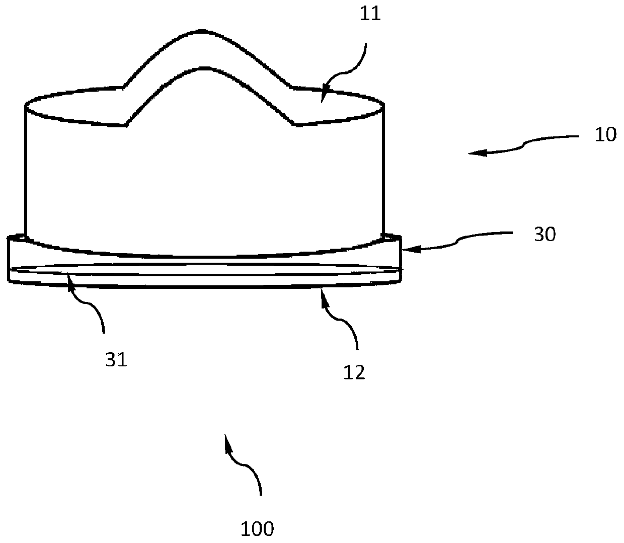
[0031] figure 1 with Figure 7 Schematic diagram of the structure of a mechanical valve on an artificial ring for mitral valve replacement.

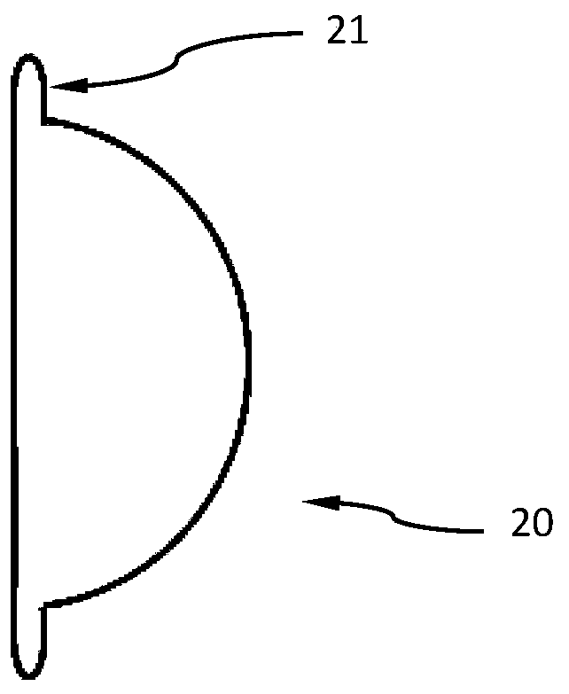
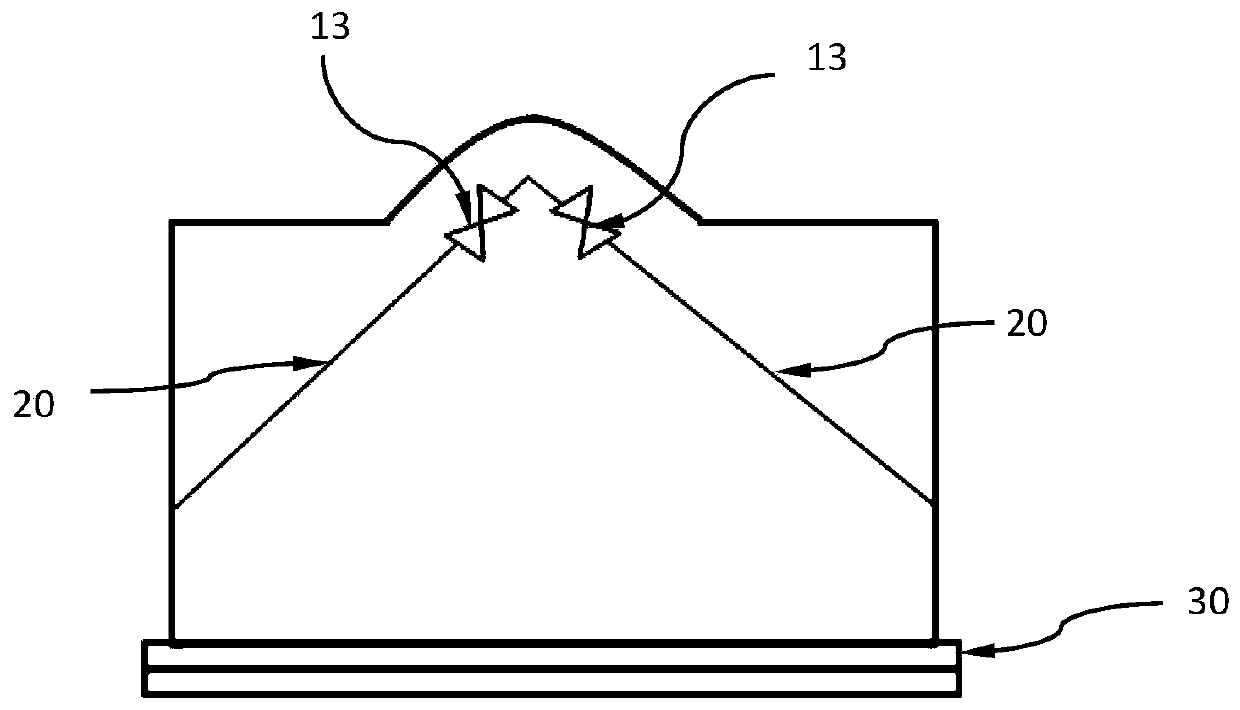
[0032] Such as figure 1 and Figure 7 As shown, the artificial supraannular mechanical valve 100 for mitral valve replacement in this embodiment has a valve frame 10 , a pair of leaflets 20 and a sewing ring 30 .

[0033] The valve frame 10 has a tubular portion in a circular tubular shape and a pair of raised portions.

[0034] The tubular portion has an inflow port portion 11 and an outflow port portion 12 through which blood f...


PUM


Abstract

The invention relates to an on-ring artificial mechanical valve for mitral valve replacement. The on-ring artificial mechanical valve is used for being implanted into the heart to replace the cardiacmitral valve with a lesion at the junction between the left atrium and the left ventricle. The valve includes a valve stent containing a tubular part and a suture ring fixed to the tubular part for suture connection with a mitral valve annulus, wherein the valve stent is matched with the mitral valve annulus in the left ventricle, and a pair of openable valve leaflets are mounted on the valve stent, contained in the tubular part and used for controlling one-way circulation of blood. The tubular part is further provided with an inflow port part and an outflow port part for blood to flow from the left atrium into the left ventricle; one end of the tubular suture ring is connected to the outflow port part, the other end of the tubular suture ring protrudes to the outside to serve as a protruding end, and the suture ring can be deformed under the situation that an external force is performed on the suture ring.

Description

technical field [0001] The invention relates to an artificial mechanical valve, in particular to an annulus mechanical valve used for replacing a mitral valve. Background technique [0002] Heart valves include mitral valve, tricuspid valve, aortic valve and pulmonary valve. The mitral valve is located between the left atrium and left ventricle, and is used to ensure the one-way flow of blood from the left atrium to the left ventricle. Mitral valve disease is one of the common heart valve diseases, and its etiology includes rheumatic, degenerative and infective endocarditis, etc. Mitral valve mechanical valve replacement is a common treatment for heart mitral valve disease . [0003] The mitral valve includes leaflets, valve ring, chordae, papillary muscles and the left ventricular wall attached to the papillary muscles. During valve replacement, how to deal with the diseased valve will directly affect the prognosis and recovery of the patient. In order to implant an artif...

Claims


Application Information

Patent Timeline
Patent Type & Authority Applications(China)
IPC IPC(8): A61F2/24
CPCA61F2/2412A61F2/2418A61F2/2442A61F2/2463A61F2220/0075
Inventor 唐杨烽徐志云唐昊
Owner 中国人民解放军海军军医大学第一附属医院
Why Eureka
Try Eureka