
Eddy flow partition flotation machine
A flotation machine and flotation cell technology, applied in flotation, solid separation, etc., can solve problems affecting flotation effect, excessive turbulence in flow field, ore particle shedding, etc., to achieve flotation effect guarantee and flotation efficiency Guaranteed effect
- Summary
- Abstract
- Description
- Claims
- Application Information
AI Technical Summary
Problems solved by technology
Method used
Image

Examples
Embodiment Construction
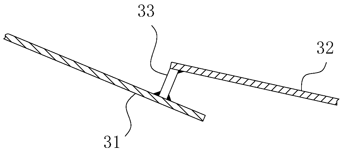
[0028] For ease of understanding, combined here Figure 1-4 , the specific embodiments of the present invention are further described as follows:
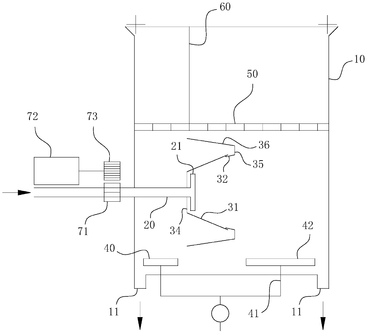
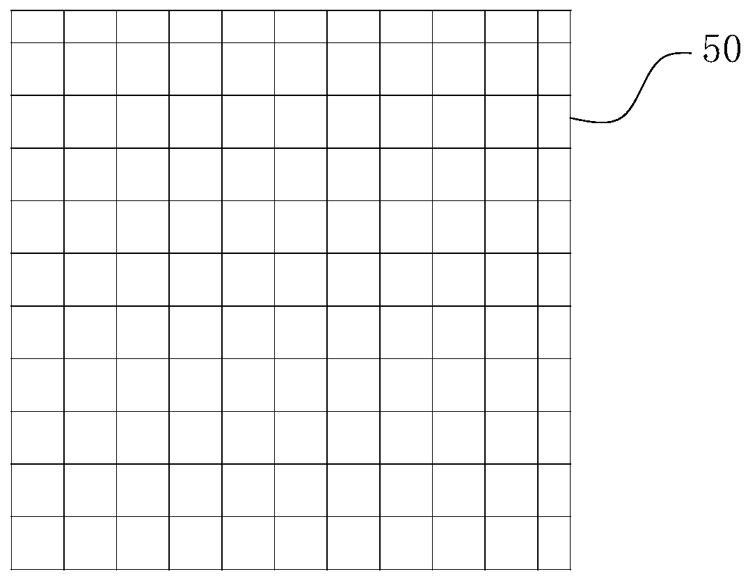
[0029] The specific components of the present invention are as follows Figure 1-4 The structure shown is an example, which is divided into several major modules, including: flotation cell 10, vertical partition 60, steady flow plate 50, rotating disk, bubble generating tube 40, rotating discharge tube 20 and driving components. in:
[0030] exist figure 1In the shown structure, the flotation cell 10 is in the shape of a square cell. In the cavity of the flotation cell 10, a vertical partition 60, a steady flow plate 50, a rotating disk and a bubble generating tube 40 are respectively arranged from top to bottom. On the left side and the right side of the bottom of the flotation tank 10, discharge pipelines 11 are respectively arranged. For the driving assembly, it includes a driving motor 72 , a driving gear 73 and a driven g...
PUM
 Abstract
Description
Claims
Application Information