
A continuous die-cutting and arranging equipment for polarizer and its production process

A polarizer and die-cutting technology, used in metal processing, thin material handling, transportation and packaging, etc., can solve the problems of difficult operation, small size, and lack of regular collection of polarizers.

Active Publication Date: 2020-10-02
惠州市富丽电子有限公司
View PDF10 Cites 0 Cited by
  • Summary
  • Abstract
  • Description
  • Claims
  • Application Information

AI Technical Summary

Problems solved by technology

[0003] When cutting the polarizer, it is first necessary to place a roll of polarizer (coil) on the machine, and then unwind it. During the unwinding process, the polarizer is pulled out to move, and the cutting knife on the machine cuts the roll The material is cut into multiple single-piece polarizers (sheets), usually by die-cutting. The existing equipment can automatically die-cut the polarizers, but none of them can collect the cut polarizers in a regular manner. Because the number of cut polarizers of this type is relatively large, and the specifications are relatively small, and the thickness is thin, it is generally arranged manually and requires very meticulous operations, so the operation is difficult and time-consuming, which greatly affects work efficiency.

Method used


Image

  • A continuous die-cutting and arranging equipment for polarizer and its production process
  • A continuous die-cutting and arranging equipment for polarizer and its production process
  • A continuous die-cutting and arranging equipment for polarizer and its production process

Examples


Embodiment 1

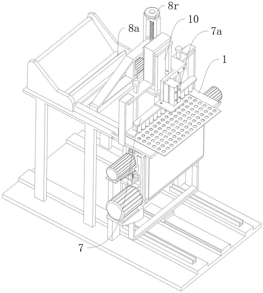
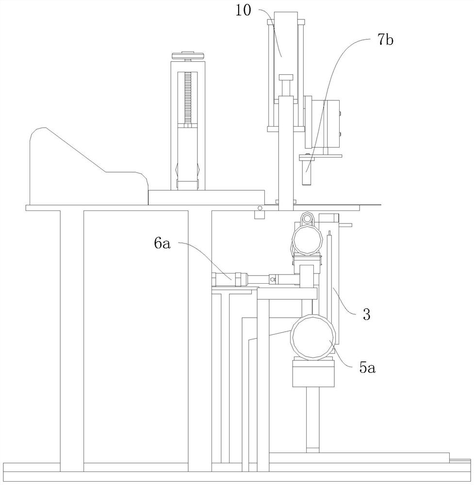
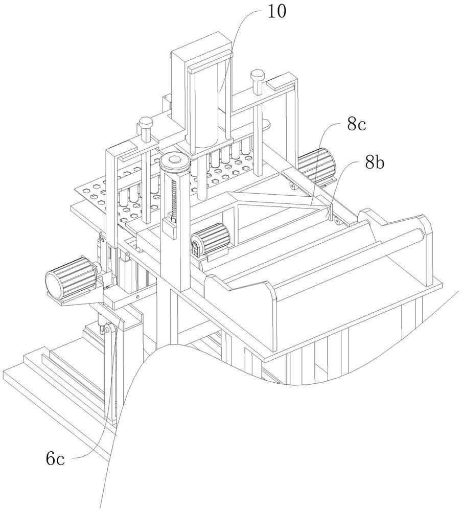
[0049] refer to Figure 1 to Figure 11 A continuous die-cutting and finishing equipment for polarizers is shown, including a controller, a processing table 1, an unwinding mechanism, a die-cutting mechanism 10, an unloading mechanism, and a regularizing mechanism sequentially arranged on the processing table 1 along a straight line , the distance between the unloading mechanism and the die-cutting mechanism 10 is between 2.5cm and 3.5cm, the downstream end of the processing table 1 is provided with a discharge slot 1a, and the regularizing mechanism includes a replacement slot installed directly below the discharge slot 1a. Plate 2, the storage component arranged on the side of the replacement plate 2, and the shifting component arranged above the replacement plate 2, and the lower part of the replacement plate 2 is provided with a lifting component for driving it to move vertically into the discharge slot 1a, A position sensor 1b electrically connected to the controller is in...

Embodiment 2

[0059] The production process of the continuous die-cutting and finishing equipment of the polarizer described in embodiment 1 comprises the following steps:

[0060] Step 1. Unwind the rolled polarizer step-by-step by the unwinding mechanism. During the process, two side limit platens 9 form the anti-wrinkle limit on both sides. Finally, the unwinding end is step-by-step. Delivered to directly below the die-cutting mechanism 10;

[0061] Step 2, the die-cutting mechanism 10 starts to work, and performs die-cutting on the polarizer directly below it. After the die-cutting is completed, the unwinding mechanism transports the die-cut part of the polarizer to the area of ​​the discharge slot 1a step by step, and then At this time, this area is filled by the replacement plate 2, so as to support the transported polarizer;

[0062] Step 3. The unloading mechanism presses down the multiple independent polarizers that have been die-cut in step 2, so that they are completely separate...


PUM


Abstract

The invention relates to the technical field of polaroid preparation, in particular to continuous die cutting and arranging equipment for polaroids and a production technology thereof. The continuousdie cutting and arranging equipment for the polaroids comprises a controller, a machining workbench, an unwinding mechanism, a die cutting mechanism, an unloading mechanism and an arranging mechanism,and the unwinding mechanism, the die cutting mechanism, the unloading mechanism and the arranging mechanism are sequentially arranged on the machining workbench along the linear sequence; the interval distance between the unloading mechanism and the die cutting mechanism is between 2.5 cm and 3.5 cm; the downstream end of the machining workbench is provided with an unloading gap groove; the arranging mechanism comprises a replacing plate installed under the unloading gap groove, a storing assembly arranged beside the replacing plate and a material poking assembly arranged over the replacing plate, and a lifting assembly used for driving the replacing plate to vertically move to the unloading gap groove is arranged under the replacing plate; and a position sensor which is electrically connected with the controller is installed on one side of the interior of the unloading gap groove. According to the continuous die cutting and arranging equipment for the polaroids and the production technology thereof, the cut polaroids can be automatically collected in a unified mode, full-automatic connection of polaroid unwinding and full-automatic die cutting and arranging is achieved, and the production efficiency of the polaroids is greatly improved.

Description

technical field [0001] The invention relates to the technical field of polarizer preparation, in particular to a continuous die-cutting and finishing equipment for polarizers and a production process thereof. Background technique [0002] The full name of polarizer is polarizer. The imaging of liquid crystal display must rely on polarized light. All liquid crystals have two front and rear polarizers attached to the liquid crystal glass to form a liquid crystal sheet with a total thickness of about 1mm. If any one is missing Polarizers and LCDs cannot display images. [0003] When cutting the polarizer, it is first necessary to place a roll of polarizer (coil) on the machine, and then unwind it. During the unwinding process, the polarizer is pulled out to move, and the cutting knife on the machine cuts the roll The material is cut into multiple single-piece polarizers (sheets), usually by die-cutting. The existing equipment can automatically die-cut the polarizers, but none ...

Claims


Application Information

Patent Timeline
Patent Type & Authority Patents(China)
IPC IPC(8): B26F1/40B26D7/32B65H75/24B65H20/02B65H23/34
Inventor 许泽林
Owner 惠州市富丽电子有限公司
Learn More