
Rock anchor beam underground workshop excavation construction method under high ground stress condition

A technology of underground powerhouse and construction method, which is applied in excavation, artificial islands, water conservancy projects, etc. It can solve the problems of unfavorable surrounding rock stable rock platform forming quality, stress adjustment and relaxation damage, relaxation and collapse, etc., to ensure stability and formation The effect of quality, reduced damage, and reduced time to stress release

Inactive Publication Date: 2019-05-21
SINOHYDRO BUREAU 7 CO LTD
View PDF3 Cites 3 Cited by
  • Summary
  • Abstract
  • Description
  • Claims
  • Application Information

AI Technical Summary

Problems solved by technology

During the blasting process of the rock platform, the side wall below the lower inflection point will be disturbed. At the same time, it will be affected by the high ground stress and it will take a long time to support the side wall system below the inflection point. Stress adjustment and slack failure for a long time will cause the side to fall off, loose and collapse, which is not conducive to the stability of the surrounding rock and the quality of the formation of the rock platform

Method used


Image

  • Rock anchor beam underground workshop excavation construction method under high ground stress condition
  • Rock anchor beam underground workshop excavation construction method under high ground stress condition
  • Rock anchor beam underground workshop excavation construction method under high ground stress condition

Examples


Embodiment Construction

[0021] The present invention is further described below in conjunction with specific embodiment, and specific embodiment is the further description of the principle of the present invention, does not limit the present invention in any way, and the identical or similar technology of the present invention all does not exceed the scope of protection of the present invention.

[0022] In conjunction with the accompanying drawings.

[0023] combine Figure 1 to Figure 2 .

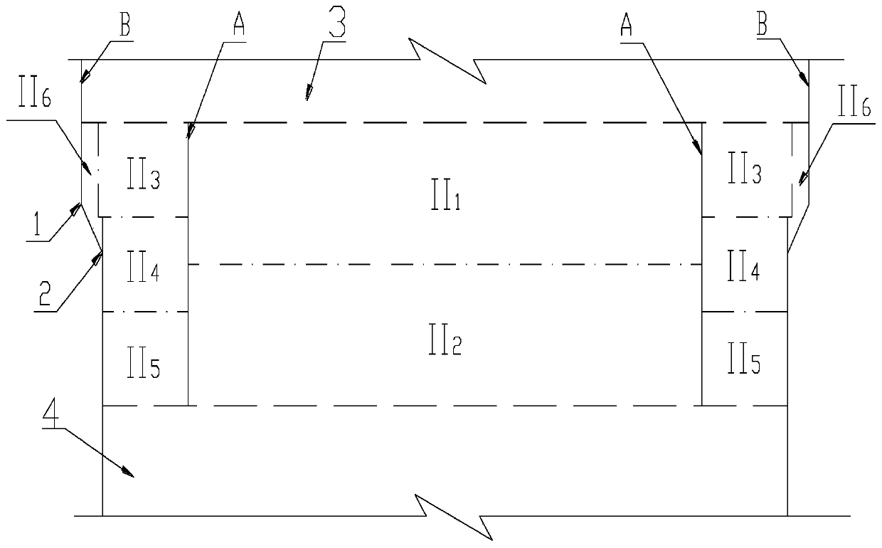
[0024] The excavation of the rock anchor beam layer is divided into the upper layer of the middle groove, the upper layer of the protective layer, the lower layer of the middle groove, the middle layer of the protective layer, the lower layer of the protective layer and the excavation of the triangular body of the rock platform;

[0025] Pre-crack the protective layer on both sides of the rock anchor beam and the groove edge of the middle groove to form two pre-cracks. The pre-splitting holes between the protec...


PUM

PropertyMeasurementUnit
Hole depthaaaaaaaaaa
Hole spacingaaaaaaaaaa

Abstract

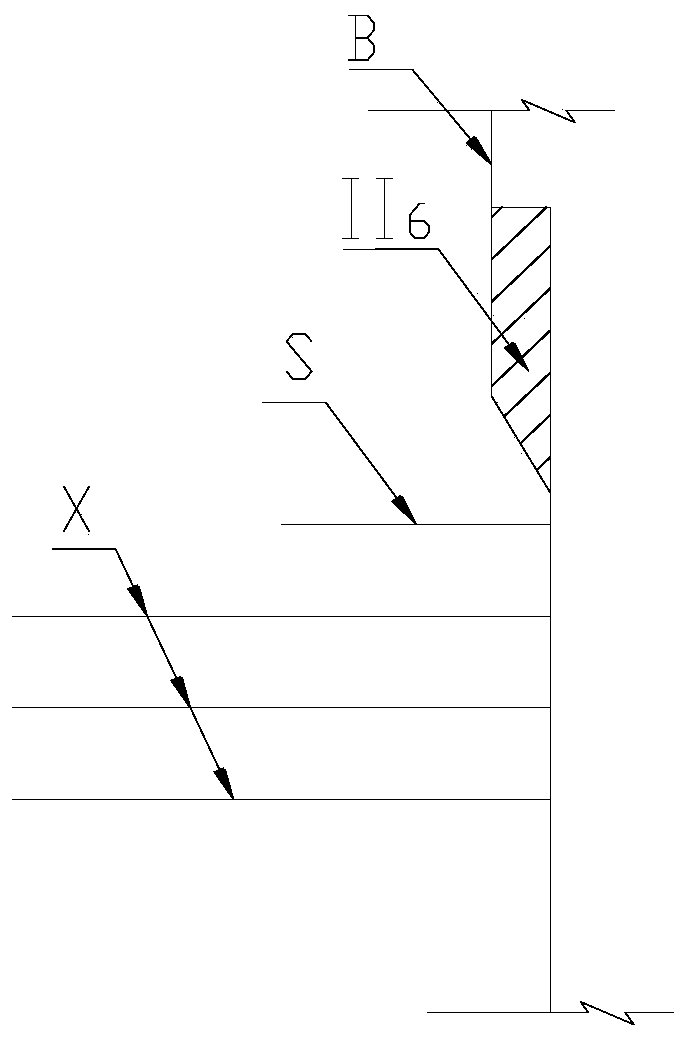
The invention discloses a rock anchor beam underground workshop excavation construction method under a high ground stress condition. Cavern excavation is divided into shallow layer excavation, rock anchor beam section excavation and deep layer excavation in sequence. The rock anchor beam section excavation comprises excavation above an upper inflection point of a rock anchor beam section and excavation below a lower inflection point of the rock anchor beam section from top to bottom, and is divided into a middle groove and protection layers on two sides according to the cross section, whereinthe middle groove is divided into an upper layer and a lower layer for excavation, the protection layers on two sides are each divided into an upper layer, a middle layer and a lower layer for excavation, and the middle layer of each protection layer at least covers the lower inflection point. After excavation of the lower layers of the protection layers on two sides is completed, side wall structural surface system supporting is conducted immediately, the side wall rock exposure and stress release time is shortened, rock anchoring is completed in time, and the side wall stability and the forming quality are guaranteed. A row of locking anchor rods are additionally arranged at the position of the lower inflection point before a rock table triangular body is excavated, rock mass anchoring at the position is completed in advance, damage to the lowest inflection point and surrounding rock masses caused by blasting vibration is reduced, and the rock table forming quality is guaranteed.

Description

technical field [0001] The invention belongs to the technical field of water conservancy and hydropower engineering, in particular to the technical field of rock anchor beam excavation in underground caverns, and specifically relates to a construction method for excavating rock anchor beam underground powerhouse caverns under high ground stress conditions. Background technique [0002] The rock anchor beam is the abbreviation of the rock wall crane beam. The reinforced concrete beam is anchored to the rock by a long grouted anchor at a certain depth. The load it bears is transmitted to the rock mass through the friction between the long anchor and the rock wall. Compared with ordinary cast-in-place beams, rock anchor beams do not set up columns and make full use of the bearing capacity of the surrounding rock. Rock anchor beams are mainly used in the installation and maintenance of electromechanical equipment in underground workshops of large-scale water conservancy projects...

Claims


Application Information

Patent Timeline
IPC IPC(8): E02D17/04E02D29/045
Inventor 刘培伟张学彬王峻王焕强王再强李旭东李霞李成伟张华武郑尧陈林
Owner SINOHYDRO BUREAU 7 CO LTD
Learn More