
Energy consumption connecting structure for connecting frame and swing wall

A technology for connecting frames and connecting structures, applied in the direction of walls, building components, building structures, etc., can solve the problems of high construction cost, complex construction, non-replacement, etc., and achieve the effect of convenient construction operation, improved bearing capacity, and simple structure

Pending Publication Date: 2019-05-21
LIAONING TECHNICAL UNIVERSITY
View PDF0 Cites 5 Cited by
  • Summary
  • Abstract
  • Description
  • Claims
  • Application Information

AI Technical Summary

Problems solved by technology

[0004] In order to solve the technical problems existing in the prior art that the connection structure is complicated, construction is inconvenient, construction cost is high, it cannot be replaced, and when an earthquake occurs, the entire structure can only be driven back to its position by the swing inertia of the swing wall itself, the present invention provides An energy-dissipating connecting structure connecting the frame and the swinging wall has a simple structure, convenient construction and operation, easy replacement and low cost. It can not only realize the return of the structure, but also dissipate part of the seismic energy input into the structure. At this time, the return of the structure can be realized through the inertia of the swing wall itself and the elastic potential energy of the spring, which can not only improve the bearing capacity of the frame swing wall structure, effectively control the structural shock damage and residual deformation, but also easily replace damaged components by adjusting the connection structure , reduce post-earthquake repair costs and repair time, and improve the earthquake resistance and disaster prevention resilience of buildings

Method used


Image

  • Energy consumption connecting structure for connecting frame and swing wall
  • Energy consumption connecting structure for connecting frame and swing wall
  • Energy consumption connecting structure for connecting frame and swing wall

Examples


Embodiment Construction

[0023] The following will clearly and completely describe the technical solutions in the embodiments of the present invention with reference to the accompanying drawings in the embodiments of the present invention. Obviously, the described embodiments are only part of the embodiments of the present invention, not all of them. In the description of the present invention, it should be noted that the orientation or positional relationship indicated by the terms "upper", "lower", "inner", "outer", "one end", "another end" etc. are based on the The orientation or positional relationship is only for the convenience of describing the present invention and simplifying the description, but does not indicate or imply that the device or element referred to must have a specific orientation, be constructed and operated in a specific orientation, and therefore cannot be construed as limiting the present invention . In addition, the terms "first" and "second" are used for descriptive purpose...


PUM


Abstract

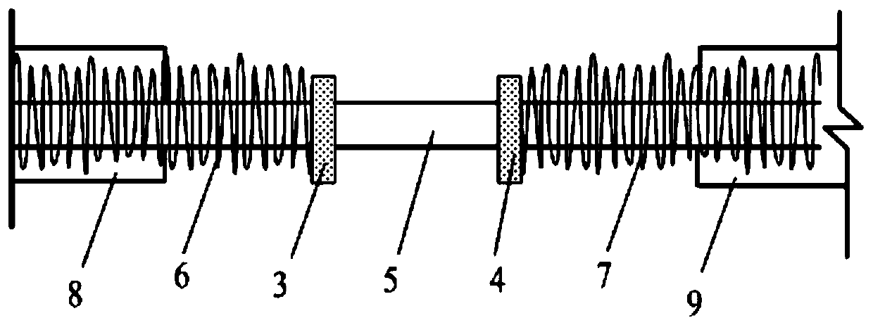
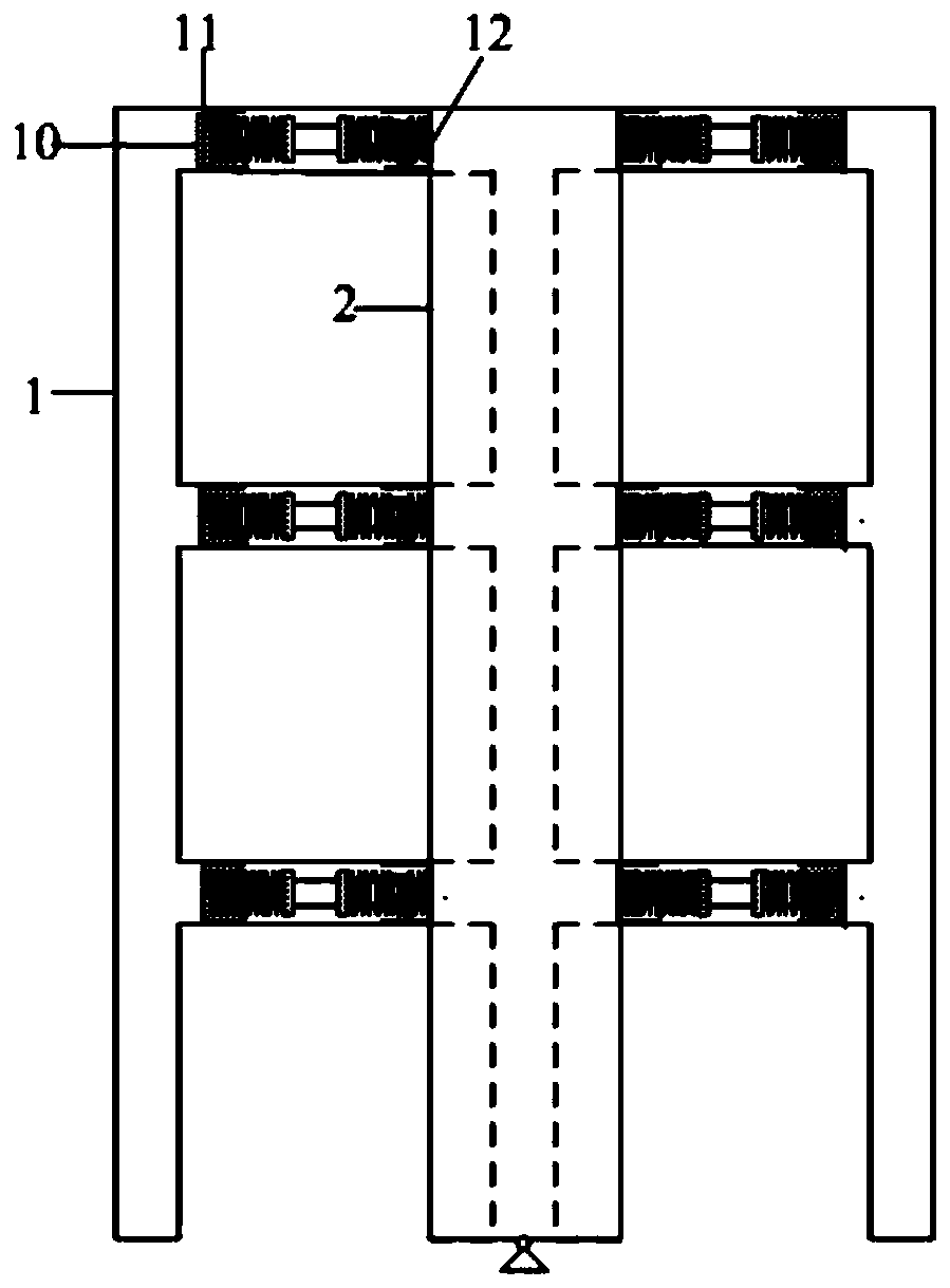
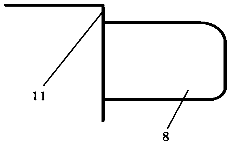
The invention discloses an energy consumption connecting structure for connecting a frame and a swing wall and belongs to the technical field of civil engineering earthquake resistance and shock absorption. The energy consumption connecting structure for connecting the frame and the swing wall comprises a screw rod, a nut I and a nut II are symmetrically arranged in the middle of the screw rod. The end, close to the first nut, of the screw rod is sleeved by a first spring, the end, close to the second nut, of the screw rod is sleeved by a second spring, one end of the first spring makes contact with the first nut, the other end of the first spring is located in a first sleeve, one end of the second spring makes contact with the second nut, and the other end of the second spring is locatedin a second sleeve. The energy consumption connecting structure for connecting the frame and the swing wall is simple in structure, convenient to construct and operate, easy to replace and low in cost, the structure can be reset, part of earthquake energy in an input structure can be dissipated, the bearing capacity of the frame-swing wall structure can be improved, and the structure shock loss and residual deformation can be effectively controlled.

Description

technical field [0001] The invention relates to the field of anti-seismic and shock-absorbing technology of civil engineering, in particular to an energy-dissipating connection structure connecting a frame and a swing wall. Background technique [0002] The frame structure, especially the concrete frame, is prone to storey yield failure caused by hinged column ends during earthquakes, which is the main failure mode of the concrete frame. The column is the main component bearing the vertical load, and the failure of the column is the direct cause of the collapse of the structure. Therefore, the story yield failure caused by the hinge at the end of the column is not conducive to the improvement of the seismic performance of the structure. In addition, the number of plastic hinges in the layer yield mechanism is small, and the energy dissipation capacity is small; under the action of axial compression, the deformation capacity and energy dissipation capacity of column hinges ar...

Claims


Application Information

Patent Timeline
Patent Type & Authority Applications(China)
IPC IPC(8): E04B1/98E04H9/02E04B2/00
Inventor 刘书贤聂伟路沙沙白春刘少栋尹航谢宇航张春华梁天宝聂莉
Owner LIAONING TECHNICAL UNIVERSITY
Learn More