Breeze generator

A generator and breeze technology, which is applied to wind turbines, wind turbine combinations, wind turbine control, etc., can solve the problems of low wind energy conversion efficiency, limited frontal area of ​​wind blades, and difficulty in generating electricity from wind turbines, so as to improve the conversion rate. , The effect of improving the driving performance and reducing the resistance

Active Publication Date: 2019-05-21
GUANGZHOU ZHUOYUE POWER NEW ENERGY CO LTD
View PDF6 Cites 0 Cited by
  • Summary
  • Abstract
  • Description
  • Claims
  • Application Information

AI Technical Summary

Problems solved by technology

[0006] Aiming at the technical problems that current vertical axis wind generators have limited frontal area of ​​wind blades, low wind energy conversion efficiency and low wind speed, wind generators are difficult to generate electricity, the present invention provides a breeze generator

Method used


Image

  • Breeze generator

Examples


Embodiment 1

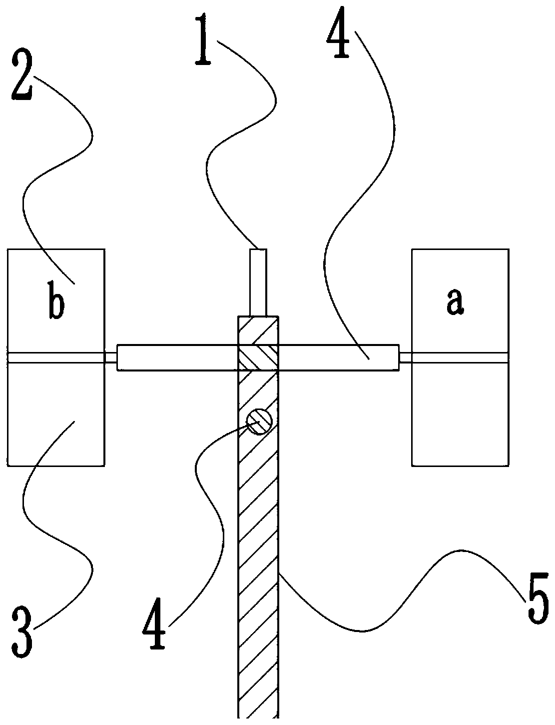
[0037] Such as figure 1 As shown, a kind of breeze generator comprises multiple sets of facing and vertically arranged wind blades 1, a plurality of connecting rods 4 arranged horizontally from bottom to top, a vertically arranged transmission shaft 5 with a hollow interior, and a power generating Machine, transmission unit, drive unit and control unit, one connecting rod 4 corresponds to a set of wind blades 1 facing oppositely.

[0038] Each wind blade 1 is composed of an upwind blade 2 and a downwind blade 3. The upwind blade 2 and the downwind blade 3 are hinged. The hinge is a one-way hinge point, and the hinge angle is 0°-180°. 2 is a reference object, and the downwind blade 3 can rotate clockwise relative to the upwind blade 2 .

[0039] Adjacent connecting rods 4 are perpendicular to each other, and each connecting rod 4 passes through the transmission shaft 5, and each connecting rod 4 can freely rotate along its own circumferential direction relative to the transmis...

Embodiment 2

[0051] The difference from Embodiment 1 is that in this embodiment, the breeze generator includes a pit installed under the generator. A touch switch is installed between the upwind blade and the downwind blade. The position of the touch switch is the position of the one-way handover point. An electric push rod supporting the generator is installed below the generator. When the upwind blade and the downwind blade are completely closed, the touch switch is triggered, the electric push rod is activated, and the electric push rod shrinks downward to drive the whole breeze generator into the pit. A temperature sensor is installed on the back side of the wind direction sensor, that is, on the opposite side of the wind blade where the wind direction sensor is installed, and the temperature sensor is electrically connected to the microcontroller. When the temperature sensor detects that the temperature is higher than the preset temperature value of the microcontroller, the microcon...


PUM


Abstract

The invention belongs to the technical field of generator production, and particularly relates to a breeze generator. The breeze generator comprises a plurality of sets of blades, a plurality of connecting rods, a generator body, a transmission unit, a driving unit, a wind transducer and a microcontroller, wherein the blades directly face one another and are arranged vertically, and the connectingrods are horizontally arranged in sequence from bottom to top. Each blade is composed of an upper blade body and a lower blade body, wherein the upper blade body and the lower blade body are hinged together, and the hinge point is a one-way hinge point. Every two adjacent connecting rods are perpendicular to each other, and the two ends of each connecting rod are fixedly connected with the one-way hinge points of the corresponding blades. The generator body is fixedly connected with a transmission shaft, and the connecting rods can freely rotate relative to the transmission shaft and can drive the transmission shaft to rotate in the circumferential direction. The driving unit is used for driving the connecting rods to rotate by one circle. The transmission unit is used for transmitting the motion between every two adjacent connecting rods. The wind transducer is used for detecting the wind direction of natural wind. The microcontroller controls the driving unit to be started or not tobe started according to data acquired by the wind sensor. The breeze generator is suitable for a region where the annual average wind speed is 3m / s-3.5m / s.

Description

technical field [0001] The invention relates to the technical field of generators, in particular to a breeze generator. Background technique [0002] Wind energy, as a clean and renewable energy, has attracted more and more attention from all over the world; the use of wind energy is inseparable from wind turbines. There are two types of current wind turbines: 1. Horizontal axis wind turbines; 2. Vertical axis wind turbines. shaft wind turbine. [0003] Compared with horizontal axis wind turbines, vertical axis wind turbines have the advantages of no need for yaw, light wind start, and no noise. m / s; Breeze start means that the start-up wind speed of the wind turbine is 3.4-5.4m / s. [0004] However, the known vertical axis wind power generators at present all use the vertical single-blade structure to drive the generator to generate electricity. To reach 4.2m / s, the annual average wind speed of not less than 5m / s is required to establish a wind power station according to ...

Claims


Application Information

Patent Timeline
Patent Type & Authority Applications(China)
IPC IPC(8): F03D9/25F03D3/06F03D7/06F03D15/00H02K7/18
CPCY02E10/74Y02P70/50
Inventor 何幸华黎少伟李政文何可立马俊
Owner GUANGZHOU ZHUOYUE POWER NEW ENERGY CO LTD
Why Eureka
Try Eureka