Permanent magnet hall thruster ignition device

A Hall thruster and ignition device technology, applied in the direction of thrust reverser, machine/engine, and plasma utilization, can solve the problems of wasting space resources, difficulty for electrons to enter the discharge channel, and difficult realization of thruster arcing, etc., to achieve The effect of convenient arc starting and saving space resources

Pending Publication Date: 2019-05-21
NANHUA UNIV
View PDF11 Cites 1 Cited by
  • Summary
  • Abstract
  • Description
  • Claims
  • Application Information

AI Technical Summary

Problems solved by technology

[0005] However, the magnetic field at the outlet of the discharge channel 3 of the above-mentioned low-power permanent magnet Hall thruster is generally greater than 200Gs. Arc is more difficult to achieve
At present, methods such as increasing the anode voltage and increasing the anode flow rate are mainly used to realize the ignition of the permanent magnet Hall thruster. However, the conditions such as high voltage and large flow rate used in this ignition method not only waste limited space resources, but also have a negative impact on the electric propulsion system. The development of other corresponding components (such as power processing unit, propellant storage and supply unit and control unit, etc.) puts forward higher requirements, which will adversely affect the test and application of the permanent magnet Hall thruster

Method used


Image

  • Permanent magnet hall thruster ignition device
  • Permanent magnet hall thruster ignition device
  • Permanent magnet hall thruster ignition device

Examples


Embodiment Construction

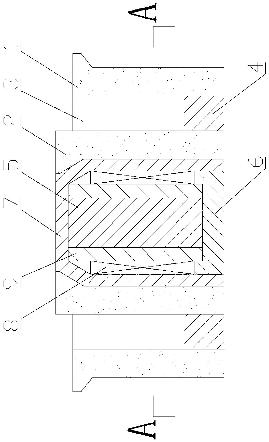
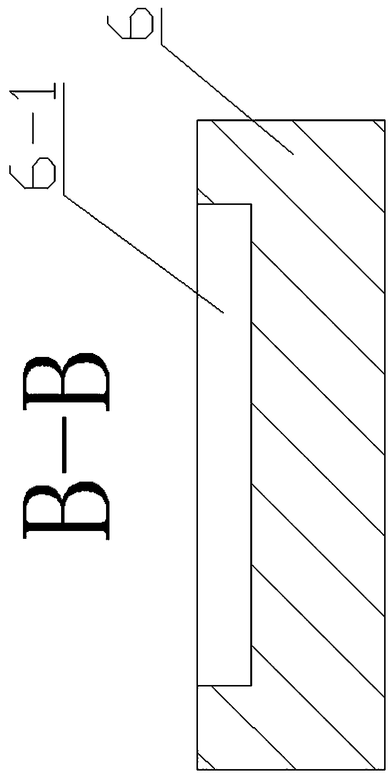
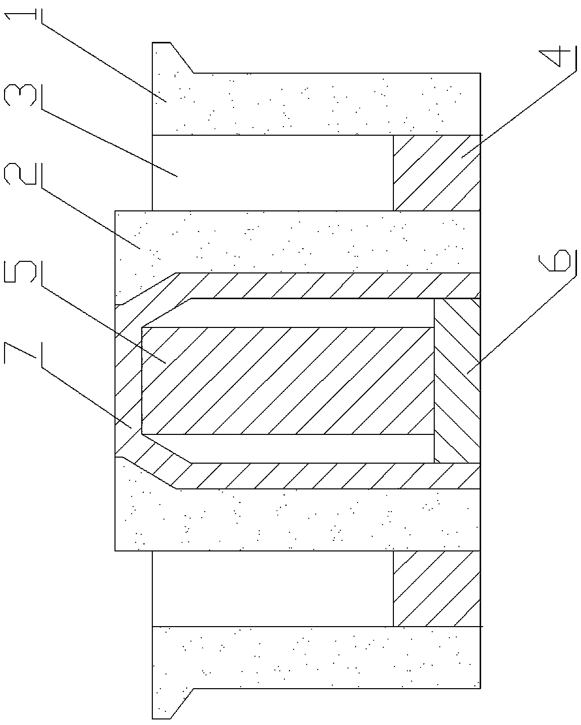
[0023] Examples such as Figure 1-4 As shown, the permanent magnet Hall thruster ignition device includes an outer ceramic ring 1 , an inner ceramic ring 2 , an anode assembly 4 , a magnetic steel 5 , a magnetically conductive base 6 and a magnetic steel sleeve 7 . The outer wall of the anode assembly 4 is installed on the lower end of the inner wall of the outer ceramic ring 1 by extrusion, and the lower end of the outer wall of the inner ceramic ring 2 is installed on the inner wall of the anode assembly 4 by extrusion, between the inner wall of the outer ceramic ring 1 and the outer wall of the inner ceramic ring 2 An annular discharge channel 3 is formed, the magnetic steel sleeve 7 is installed on the inner wall of the inner ceramic ring 2 by extrusion, the outer wall of the magnetic base 6 is installed on the lower end of the inner wall of the magnetic steel sleeve 7 by extrusion, and the magnetic steel 5 is installed on the magnetic In the steel sleeve 7 , the upper end...


PUM


Abstract

The invention discloses a permanent magnet hall thruster ignition device comprises an outer ceramic ring, an inner ceramic ring, an anode assembly, magnetic steel, a magnetic conductive base, a magnetic steel sleeve, excitation coils and a magnetic conductive ferrule; the magnetic conductive ferrule is installed on the outer wall of the magnetic steel in a sleeved manner; the magnetic conductive ferrule and the magnetic steel are installed in an annular positioning ring on the magnetic conductive base; and the excitation coils are installed between the inner wall of a magnetic steel sleeve andthe outer wall of the magnetic conductive ferrule through positioning of the annular positioning ring. In the ignition process, the excitation coils, a power supply of which is supplied by a cathodeheating power supply, generate a magnetic field with a direction opposite to a direction of an inherent magnetic field of the magnetic steel, and the intensity of the magnetic field at an outlet of adischarge channel is weakened, so that primary electrons emitted by a cathode can successfully enter the discharge channel, and arcing ignition of the thruster is facilitated; and after ignition of the thruster is finished, power supply of the excitation coils is cut off. By adopting the permanent magnet hall thruster ignition device, the ignition difficulty of a permanent magnet hall thruster canbe remarkably lowered, and extra burden caused to components such as a power supply processing unit, a propellant storage unit and a control unit cannot be generated at the same time.

Description

technical field [0001] The invention relates to the field of aerospace electric propulsion, in particular to an ignition device for a permanent magnet Hall thruster. Background technique [0002] A typical electric propulsion system includes an electric thruster, a power processing unit, a propellant storage and supply unit, and a control unit, among which the electric thruster is the core component of the electric propulsion system. With the vigorous development of the small satellite market, the demand for high performance of low-power electric thrusters is becoming more and more urgent. The low-power permanent magnet Hall thruster has a high thrust power ratio due to the reduction of the power consumption of the excitation coil, and is an ideal choice for small satellites. One of the preferred options for the application. [0003] The axial sectional view of the existing low-power permanent magnet Hall thruster is attached Figure 5 As shown, it includes an outer ceramic...

Claims


Application Information

Patent Timeline
Patent Type & Authority Applications(China)
IPC IPC(8): F03H1/00
Inventor 龙建飞
Owner NANHUA UNIV
Why Eureka
Try Eureka