Air suction drainage structure of electric air conditioner compressor for automobile

An electric air conditioner and compressor technology, applied in the field of auto parts, can solve the problems of disordered flow state, large pressure loss and pulsation, electronically controlled ablation, etc., to avoid excessive working temperature, reduce pressure loss, and reduce airflow pulsation. Effect

Active Publication Date: 2019-05-21
郑州跃博新能源汽车科技有限公司
View PDF7 Cites 1 Cited by
  • Summary
  • Abstract
  • Description
  • Claims
  • Application Information

AI Technical Summary

Problems solved by technology

[0003] The electric control and suction port of the existing compressor structure are mostly arranged on the side of the motor. The position of the suction port only meets the requirements of the suction function. The refrigerant enters the low-pressure chamber from the suction port, and the flow in the low-pressure chamber The state is chaotic, resulting in large pressure loss and pulsation, which will directly affect the refrigeration performance of the compressor
[0004] In the existing compressor electric control and motor structure layout, there is no separate cooling system, and it can only rely on the refrigerant entering the suction port for cooling. However, the existing design does not fully consider the cooling requirements of the motor and electric control. Insufficient heat dissipation often leads to electrical control ablation or motor burnout, and the compressor is scrapped

Method used


Image

  • Air suction drainage structure of electric air conditioner compressor for automobile
  • Air suction drainage structure of electric air conditioner compressor for automobile
  • Air suction drainage structure of electric air conditioner compressor for automobile

Examples


Embodiment 1

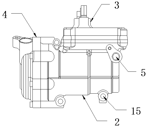
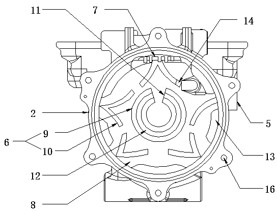
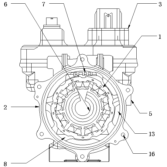
[0018] as attached Figure 1-3 As shown, the purpose of the present invention is achieved in this way: a kind of electric air-conditioning compressor suction and drainage structure for automobiles, including motor 1, motor casing 2, compressor electric control 3, pump body 4, suction port 5, suction Port diversion groove 6, electric control cooling grid 7, housing diversion groove 8, motor casing 2 is set on the motor 1, compressor electric control 3 is arranged on one side of the motor casing 2, and the One end of the motor 1 is provided with a pump body 4, one side of the motor casing 2 is provided with an air inlet 5, and the inner bottom surface of the motor casing 2 is provided with an air inlet guide groove 6, and the air inlet guide The flow groove 6 includes an annular flow guide block 9 and a herringbone flow guide block 10, the annular flow guide block 9 is provided with a gap 11, and the front of the annular flow guide block 9 is provided with an annular groove 12 ...


PUM


Abstract

The invention discloses an air suction drainage structure of an electric air conditioner compressor for an automobile. A refrigerant working medium enters an air suction opening diversion trench through an air suction opening, inverted-V-shaped diversion clamping blocks achieve the effects of separation and diversion, pressure losses and airflow pulsation on the air suction opening can be effectively reduced, then the refrigerant working medium enters a shell diversion trench and an electric controller cooling grating, then a motor and a compressor electric controller can be fully cooled, it is guaranteed that the motor and the compressor electric controller work at the required environment temperature, and when the cooling working medium passes through a specific drainage passageway, separated oil drops can effectively lubricate a rotating structure. As a whole, the air suction drainage structure has the beneficial effects that the pressure losses and the flow pulsation on the air suction opening can be reduced, and the compressor electric controller and the motor are effectively cooled by fully utilizing the flow state of the refrigerating working medium, and the problems that due to an existing electric compressor cooling structure, the flow state of the refrigerating working medium is disorderly, the pressure losses and pulsation are large, and the refrigerating performanceof the compressor is affected are effectively solved.

Description

technical field [0001] The invention belongs to the technical field of auto parts, and relates to an electric air-conditioning compressor for automobiles, in particular to an air suction and drainage structure for an electric air-conditioning compressor for automobiles. Background technique [0002] Electric compressors are widely used in the thermal management industry of new energy vehicles due to their small size, light weight, stable operation, and high volumetric efficiency. Usually, electric compressors mainly include motors, electric controls, and pumps. The main functions of the compressor in the thermal management system are suction, compression and exhaust, providing power source for the realization of the functions of the thermal management system, while in the electric compressor, the two parts of the motor and the electronic control can only be guaranteed by suction cooling. normal working environment. [0003] The electric control and suction port of the exist...

Claims


Application Information

Patent Timeline
Patent Type & Authority Applications(China)
IPC IPC(8): F04B39/06F04B39/02F04B35/04
Inventor 弋孟楷周磊
Owner 郑州跃博新能源汽车科技有限公司
Why Eureka
Try Eureka