
Fan with automatic air exchange fan

A self-ventilating and functional technology, applied in the direction of machines/engines, liquid fuel engines, pumping devices for elastic fluids, etc., can solve problems such as insufficient flexibility, low intelligence, and poor automatic ventilating effect , to achieve the effect of enhancing flexibility, improving intelligence and improving safety

Inactive Publication Date: 2019-05-21
胡恩卫
View PDF0 Cites 0 Cited by
  • Summary
  • Abstract
  • Description
  • Claims
  • Application Information

AI Technical Summary

Problems solved by technology

[0005] The purpose of the present invention is to provide a fan with automatic ventilation function to solve the problems of poor automatic ventilation effect, low intelligence and insufficient flexibility of the device proposed in the above background technology

Method used


Image

  • Fan with automatic air exchange fan
  • Fan with automatic air exchange fan
  • Fan with automatic air exchange fan

Examples


Embodiment Construction

[0018] The following will clearly and completely describe the technical solutions in the embodiments of the present invention with reference to the accompanying drawings in the embodiments of the present invention. Obviously, the described embodiments are only some, not all, embodiments of the present invention. Based on the embodiments of the present invention, all other embodiments obtained by persons of ordinary skill in the art without making creative efforts belong to the protection scope of the present invention.

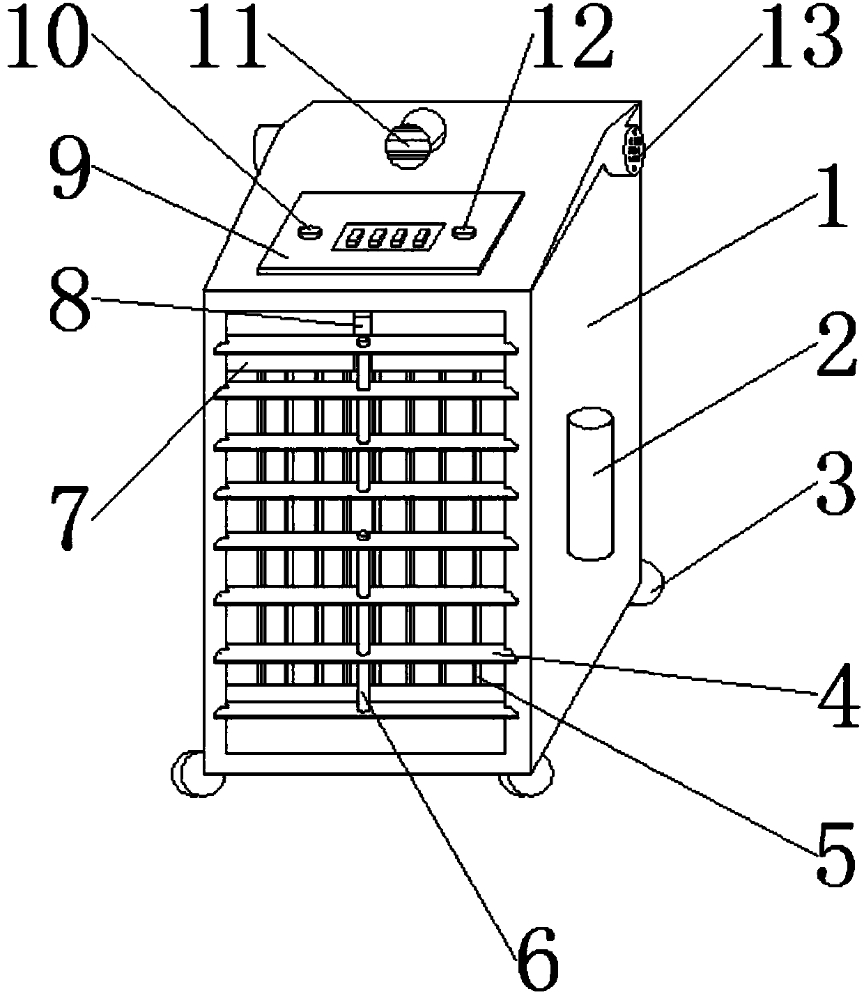
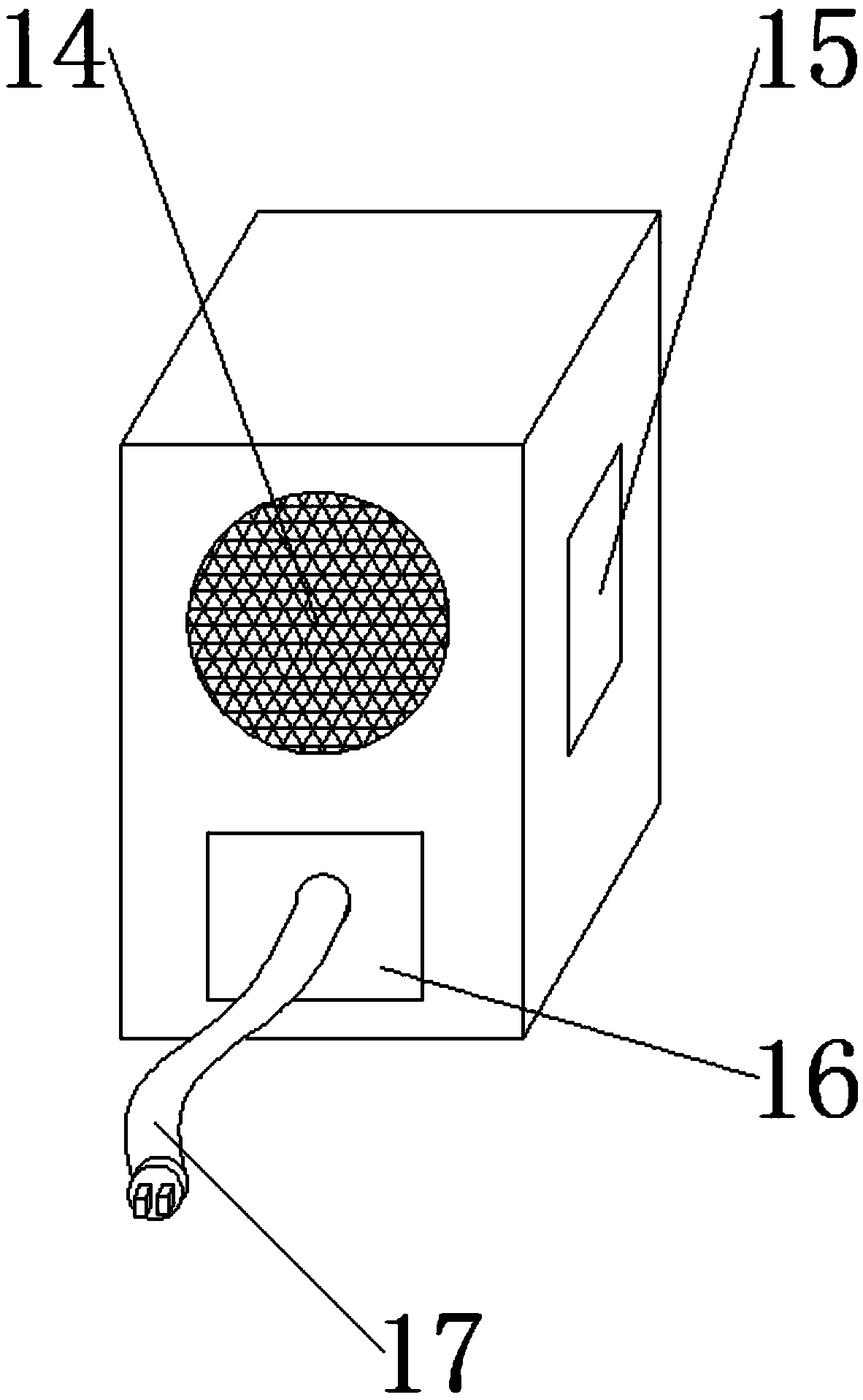
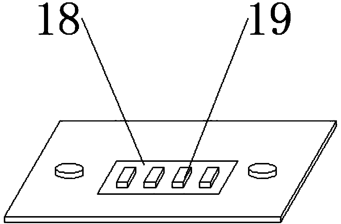
[0019] see Figure 1-3 , the present invention provides a technical solution: a fan with automatic ventilation function, including a device body 1, a longitudinal guide fan 4 is installed at the front end of the device body 1, and the longitudinal guide fan 4 is movably connected with the device body 1 , the inside of the longitudinal guide fan 4 is equipped with a transverse guide fan 5, and the transverse guide fan 5 is movably connected with the device body...


PUM


Abstract

The invention discloses a fan with an automatic air exchange function. The fan comprises a device body, a longitudinal air guide fan is installed at the front end of the device body and movably connected with the device body, a transverse air guide fan is installed inside the longitudinal air guide fan, the transverse air guide fan is movably connected to the device body, the upper and lower endsof the transverse air guide fan are provided with drivers correspondingly, and the drivers are fixedly connected with the transverse air guide fan. An air sucker and an air exhauster are arranged, when the device is operated, the air sucker and the air exhauster can intelligently suck air and exhaust air in a convection mode, the purpose that the device automatically exchanges air is achieved, a signal receiver arranged on the device can start the device under remote operationand control of a user, and device intelligence is improved;the device is provided with an intelligent screen which candisplay the energy consumption value and refrigeration and heating states of the device, device intelligence is further improved, and theuser can move the device through sliding wheels arranged on thedevice.

Description

technical field [0001] The invention relates to the technical field of automatic ventilation, in particular to a fan with automatic ventilation function. Background technique [0002] The mechanical fan originated in 1830. An American named James Byron was inspired by the structure of the clock and invented a mechanical fan that could be fixed on the ceiling and driven by a clockwork. The gentle breeze from the garden makes people feel happy, but it is troublesome to climb up the ladder to wind it up. In 1872, a Frenchman named Joseph developed a mechanical fan that was started by a clockwork turbine and driven by a gear and chain device. This fan was much more refined than the mechanical fan invented by Byron, and it was easier to use. In 11880, the United States For the first time, Ren Shule installed the blades directly on the motor, and then connected to the power supply. The blades rotated rapidly, and the cool wind rushed to the face. This is the world's first electri...

Claims


Application Information

Patent Timeline
Patent Type & Authority Applications(China)
IPC IPC(8): F04D25/08F04D27/00F04D29/00F04D29/40
Inventor 胡恩卫
Owner 胡恩卫
Learn More